DTC P0111: Intake Air Temp Performance: Testing
- Turn ignition on, engine off. Using scan tool, read DTCs. If GOOD TRIP counter for DTC P0111 is displayed and displayed count is "0", go to next step. If GOOD TRIP counter for DTC P0111 is not displayed or displayed count is not "0", go to step 7.
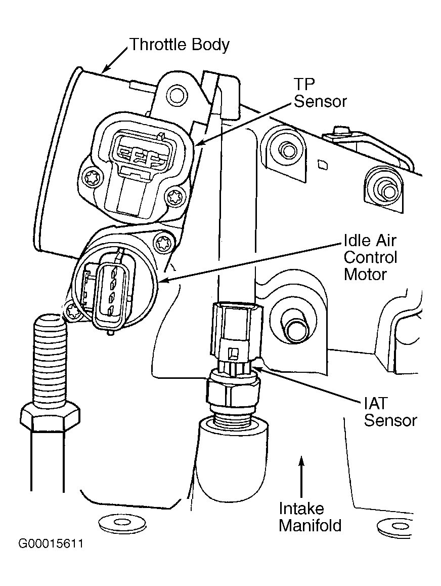
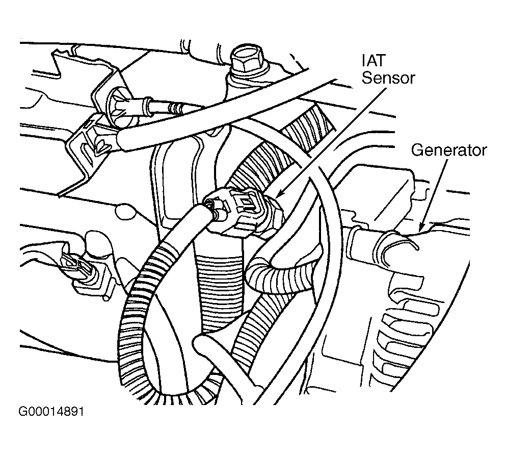
- Turn ignition off. Disconnect IAT sensor connector. On 4.7L, IAT sensor is located on intake manifold, near throttle body. See Fig 1. On 5.9L, IAT sensor is located on intake manifold. See Fig 2. Turn ignition on, engine off. Using scan tool, read IAT sensor voltage. If voltage is more than 4.6 volts, go to next step. If voltage is 4.6 volts or less, go to step 4.
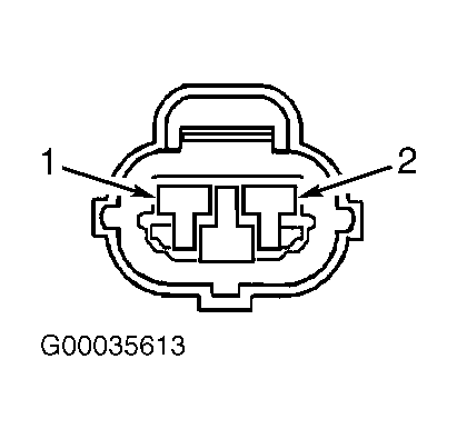
- Turn ignition off. Ensure IAT sensor is disconnected. Connect jumper wire between both IAT sensor harness connector terminals. See Fig 3. Turn ignition on, engine off. Using scan tool, read IAT sensor voltage. If voltage is one volt or more, go to next step. If voltage is less than one volt, replace IAT sensor.
- Perform voltage drop test. Using DVOM, measure voltage by backprobing IAT sensor ground circuit between IAT sensor harness connector terminal No. 1 and PCM harness connector C1 terminal No. 4. See Figure and Fig 3
. Start engine and allow to idle. If voltage is less than .10 volt, go to next step. If voltage is .10 volt or more, repair high resistance in sensor ground circuit.
- Perform voltage drop test. Using DVOM, measure voltage by backprobing IAT sensor signal circuit between IAT sensor harness connector terminal No. 2 and PCM harness connector C1 terminal No. 15. See Figure and Fig 3
. Start engine and allow to idle. If voltage is less than .10 volt, go to next step. If voltage is .10 volt or more, repair high resistance in sensor signal circuit.
- At this time, PCM is assumed to be defective. Replace PCM.
- At this time, conditions for DTC to set do not exist or fault is an intermittent problem. Start engine and allow to idle. Ensure engine is at normal operating temperature. Using scan tool, monitor parameters related to DTC while wiggling connectors and wiring harness. If value changes while wiggling connectors and wiring harness, repair connectors and wiring harness where wiggling caused value to change. If value does not change, review FREEZE FRAME DATA using scan tool. Attempt to duplicate condition that caused DTC to set. Check for any related Technical Service Bulletins (TSBs) that may apply. Visually inspect related connectors and wiring harness. Repair connectors and wiring harness as necessary. See WIRING DIAGRAMS article. If no problems are indicated, test is complete.
 Courtesy of DAIMLERCHRYSLER CORPORATION
 Courtesy of DAIMLERCHRYSLER CORPORATION
 Courtesy of DAIMLERCHRYSLER CORPORATION