DTC 94: TCS Control Valve Sensor
- Check for any PGM-FI DTC(s). With SCS Service Connector (07PAZ-0010100) connected to 2-pin service check connector, turn ignition switch to ON position (without starting engine). See Figure. Record blinking MIL sequence. See Figure. If any PGM-FI DTC(s) are present, diagnose those first. See SELF-DIAGNOSTICS - 3.5RL
(2000) or SELF-DIAGNOSTICS - 3.5RL
(2001) article in ENGINE PERFORMANCE. If no PGM-FI DTC(s) are present, go to next step.
- Disconnect TCS control valve angle sensor 3-pin connector. See Fig 1. Turn ignition on. Using DVOM, measure voltage between ground and TCS control valve angle sensor 3-pin connector terminal No. 3 (Yellow/Blue wire). See Fig 2. Reading should be approximately 5 volts. If reading is as specified, go to next step. If reading is not as specified, repair open circuit in Yellow/Blue wire between TCS control valve angle sensor connector terminal No. 3 and PCM 22-pin connector "D" terminal No. 21. See WIRING DIAGRAMS .
- Measure voltage between TCS control valve angle sensor 3-pin connector terminals No. 3 (Yellow/Blue wire) and No. 1 (Green/Black wire). Reading should be approximately 5 volts. If reading is as specified, go to next step. If reading is not as specified, repair open circuit in Green/Black wire between TCS control valve angle sensor connector terminal No. 1 and PCM 22-pin connector "D" terminal No. 22. See Figure. See WIRING DIAGRAMS .
- Turn ignition off. Disconnect VSA converter unit 26-pin connector. Using DVOM, check for continuity between ground and TCS control valve angle sensor 3-pin connector terminal No. 2 (Red wire). See Fig 2. If continuity is not indicated, go to next step. If continuity is indicated, repair short to ground in Red wire between VSA converter unit 26-pin connector terminal No. 5 and TCS control valve angle sensor 3-pin connector terminal No. 2. See WIRING DIAGRAMS .
- Check for continuity on Red wire between VSA converter unit 26-pin connector terminal No. 5 and TCS control valve angle sensor 3-pin connector terminal No. 2. See Figure and Fig 2
. If continuity is indicated, go to next step. If continuity is not indicated, locate and repair open circuit in Red wire between VSA converter unit 26-pin connector terminal No. 5 and TCS control valve angle sensor 3-pin connector terminal No. 2.
- Remove air intake duct. See Fig 1. With ignition on, apply battery voltage to TCS control valve actuator 2-pin connector terminal No. 1 (Yellow wire of actuator pigtail) and apply ground to terminal No. 2 (Gray wire of actuator pigtail). Measure voltage between ground and VSA converter unit 26-pin connector terminal No. 5 (Red wire). See Figure. There should be a smooth transition in voltage from approximately 4.5 volts to 0.5 volts as TCS control valve is closed. If voltage is not as specified, replace TCS control valve assembly. If voltage is as specified, system has returned to normal. If problem returns, replace VSA converter unit. See VSA CONVERTER UNIT .
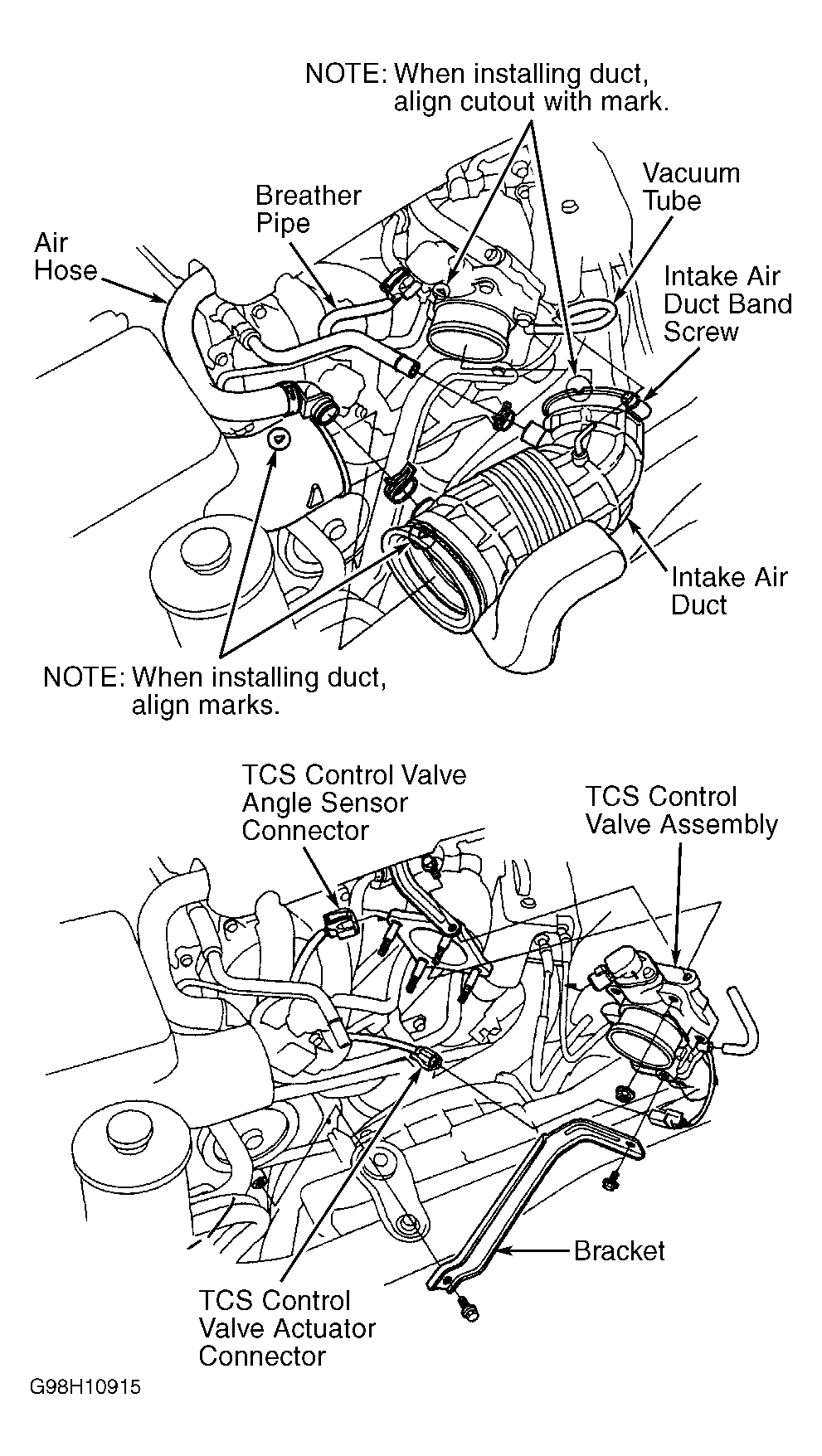 Courtesy of AMERICAN HONDA MOTOR CO., INC.
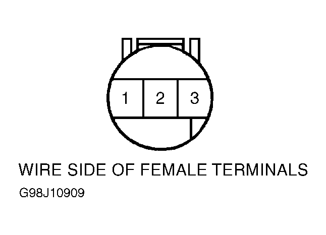 Courtesy of AMERICAN HONDA MOTOR CO., INC.