System Overview: Signals
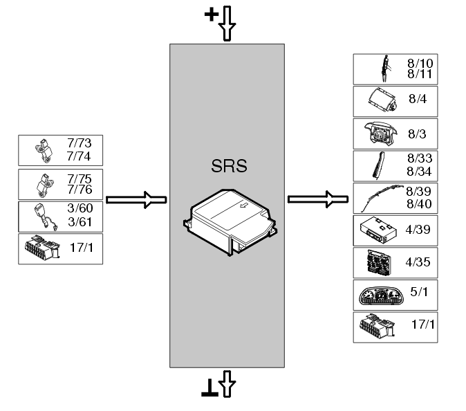
The table below summarizes the input signals to and output signals from the Supplemental Restraint System Module (SRS). The illustration below displays the same information with the Volvo component designations.
| Input signals |
Output signals |
- Side impact sensor left B-post (7/73) for detecting collisions
- Side impact sensor right B-post (7/74) for detecting collisions
- Side impact sensor left C-post (7/75) for detecting collisions
- Side impact sensor right C-post (7/76) for detecting collisions
- Seat belt buckle driver (3/60), for indication of seat belt use
- Seat belt buckle passenger (3/61), for indication of seat belt use
- Data link connector (DLC) (17/1), communication during diagnostics.
|
- Seat belt tensioner driver front (8/10)
- Seat belt tensioner passenger front (8/11)
- Airbag passenger step 1 (8/4:1), for deploying the airbag module
- Airbag passenger step 2 (8/4:2), for deploying the airbag module
- Airbag driver step 1 (8/3:1), for deploying the airbag module
- Airbag driver step 2 (8/3:2), for deploying the airbag module
- Side impact protection (SIPS) bag driver (8/33), for deploying the airbag module
- Side impact protection (SIPS) bag passenger (8/34), for deploying the airbag module
- Inflatable curtain left (8/39), for deploying the inflatable curtain
- Inflatable curtain right (8/40), for deploying the inflatable curtain
- Output signal to VGLA (Volvo guard lock and alarm system) control module (4/39), to unlock the doors in the event of a collision
- Output signal to control module for key-in warning / seat belt reminder (4/35)
- Control signal to the combined instrument panel (5/1), to light up or extinguish the SRS warning lamp
- Data link connector (DLC) (17/1), communication during diagnostics.
|
 Courtesy of VOLVO CARS OF NORTH AMERICA.