Ground Circuits
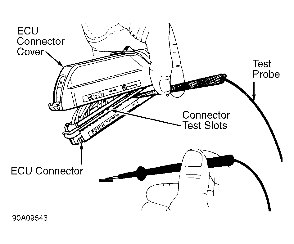
- Turn ignition off. Disconnect ECU connector. See Figure
and Fig 1
. Using DVOM, check resistance between ECU connector terminals No. 10, 20, 32 and 34 and ground. Resistance should be zero in all cases.
CAUTION:
Never probe front of connectors. Check connectors only through slots in side of connector. DO NOT use more force than necessary. See Fig 1
.
- If resistance is not correct, check wiring harness between ECU and ground connections. On 240, terminals No. 10, 20 and 34 are grounded at right heater support, below carpet. On 740 and 940, these terminals are grounded on left "A" pillar. If fault is found at terminal No. 32, retest with new solenoid valve relay. See Figure
.
 Courtesy of VOLVO CARS OF NORTH AMERICA.