Test No. 4: No Alerting Condition Exists & Anti-Theft System Cannot Be Set
- If Toyota hand-held tester is available, go to next step. If Toyota hand-held tester is not available, go to step 3.
- Connect hand-held tester to Data Link Connector (DLC) No. 3. See Figure. Using hand-held tester manufacturer's instructions, check operation of SECURITY indicator light while using the ACTIVE TEST. SECURITY indicator light is displayed as a vehicle icon near the center of the tachometer. If SECURITY indicator light does not operate properly, remove hand-held tester. Go to next step. If SECURITY indicator light operates properly, go to step 5.
- Check bulb for SECURITY indicator light. If bulb is okay, go to next step. If bulb is defective, replace bulb and recheck SECURITY indicator light and anti-theft system operation.
- Check SECURITY indicator light circuit by checking Gray wire and electrical connectors between terminal No. 11 at instrument cluster electrical connector C6 and terminal No. 17 at body Electronic Control Unit (ECU) electrical connector B7, and White/Black wire between terminal No. 6 at instrument cluster electrical connector C7 and ground connection. See WIRING DIAGRAMS
in POWER DOOR LOCKS & REMOTE KEYLESS ENTRY SYSTEMS - SEQUOIA article. For instrument cluster electrical connector and terminal identification, see Fig 1. Body ECU is located behind driver's side of instrument panel and contains 3 electrical connectors. For body ECU electrical connector terminal identification, see Figure. If wiring harness and electrical connectors are okay, go to next step. If wiring harness or electrical connector is defective, repair as necessary and recheck SECURITY indicator light and anti-theft system operation.
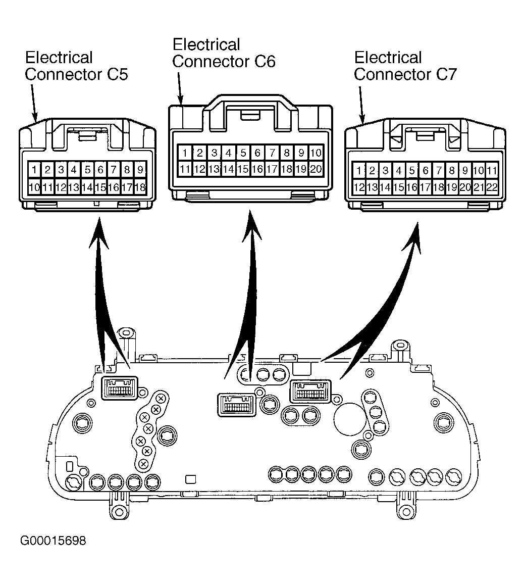 Courtesy of © TOYOTA, LICENSE AGREEMENT TMS1002
- If Toyota hand-held tester is available, go to next step. If Toyota hand-held tester is not available, go to step 7.
- With hand-held tester still connected to DLC No. 3, using hand-held tester manufacturer's instructions, check operation of key unlock warning switch while using the DATA LIST. Key unlock warning switch should be on when ignition key is in ignition lock cylinder and should be off when ignition key is removed from ignition lock cylinder. If key unlock warning switch does not operate properly, remove hand-held tester. Go to next step. If key unlock warning switch operates properly, remove hand-held tester. Go to step 9.
- Check key unlock warning switch. See KEY UNLOCK WARNING SWITCH under COMPONENT TESTS. If key unlock warning switch is okay, go to next step. If key unlock warning switch is defective, replace key unlock warning switch and recheck anti-theft system operation. See KEY UNLOCK WARNING SWITCH under REMOVAL & INSTALLATION.
- Check key unlock warning switch circuit by checking Yellow/Green wire and electrical connectors between terminal No. 2 at key unlock warning switch and terminal No. 22 at body Electronic Control Unit (ECU) electrical connector B7. See WIRING DIAGRAMS
in POWER DOOR LOCKS & REMOTE KEYLESS ENTRY SYSTEMS - SEQUOIA article. Key unlock warning switch may also be referred to as unlock switch. Body ECU is located behind driver's side of instrument panel and contains 3 electrical connectors. See Figure. For body ECU electrical connector terminal identification, see Figure. If wiring harness and electrical connectors are okay, go to next step. If wiring harness or electrical connector is defective, repair as necessary and recheck anti-theft system operation.
- Check door courtesy switch for each side door. See DOOR COURTESY SWITCH under COMPONENT TESTS. If door courtesy switches are okay, go to next step. If any door courtesy switch is defective, replace door courtesy switch and recheck anti-theft system operation.
- Check wiring harness and electrical connectors between each door courtesy switch and body ECU. See WIRING DIAGRAMS
in POWER DOOR LOCKS & REMOTE KEYLESS ENTRY SYSTEMS - SEQUOIA article. If wiring harness and electrical connectors are okay, go to next step. If wiring harness or electrical connector are defective, repair as necessary and recheck anti-theft system operation.
- If Toyota hand-held tester is available, go to next step. If Toyota hand-held tester is not available, go to step 13.
- Connect hand-held tester to DLC No. 3 if not already done. Using hand-held tester manufacturer's instructions, check operation of door unlock detection switch while using the DATA LIST for driver's side front door and passenger's side front door. Door unlock detection switch should be on when door lock knob is in the unlock position and should be off when door lock knob is in the lock position. If door unlock detection switch does not operate properly, go to next step. If both door unlock detection switches operate properly, go to step 15.
- Check door unlock detection switch on driver's side front door and passenger's side front door. See DOOR UNLOCK DETECTION SWITCH under COMPONENT TESTS. If door unlock detection switches are okay, go to next step. If any door unlock detection switch is defective, replace door lock assembly and recheck anti-theft system operation.
- Check wiring harness and electrical connectors between each door unlock detection switch and driver's door ECU or passenger's door ECU. See WIRING DIAGRAMS
in POWER DOOR LOCKS & REMOTE KEYLESS ENTRY SYSTEMS - SEQUOIA article. Driver's door ECU and passenger's door ECU are located on each door and is incorporated into the power window switch assembly. See Figure. If wiring harness and electrical connectors are okay, go to next step. If wiring harness or electrical connector are defective, repair wiring harness or electrical connector as necessary and recheck anti-theft system operation.
- If Toyota hand-held tester is available, go to next step. If Toyota hand-held tester is not available, go to step 17.
- Connect hand-held tester to DLC No. 3 if not already done. Using hand-held tester manufacturer's instructions, check operation of hood courtesy switch while using the DATA LIST. Hood courtesy switch should be on when hood is opened and should be off when hood is closed. If hood courtesy switch does not operate properly, remove hand-held tester. Go to next step. If hood courtesy switch operates properly, go to step 19.
- Check hood courtesy switch. See HOOD COURTESY SWITCH under COMPONENT TESTS. If hood courtesy switch is okay, go to next step. If hood courtesy switch is defective, replace hood courtesy switch and recheck anti-theft system operation.
- Check wiring harness and electrical connectors between hood courtesy switch and body Electronic Control Unit (ECU), and between hood courtesy switch and ground connection. See WIRING DIAGRAMS
in POWER DOOR LOCKS & REMOTE KEYLESS ENTRY SYSTEMS - SEQUOIA article. Hood courtesy switch may also be referred to as engine hood courtesy switch. Body ECU is located behind driver's side of instrument panel and contains 3 electrical connectors. See Figure. For body ECU electrical connector terminal identification, see Figure. If wiring harness and electrical connectors are okay, go to next step. If wiring harness or electrical connector is defective, repair as necessary and recheck anti-theft system operation.
- If Toyota hand-held tester is available, go to next step. If Toyota hand-held tester is not available, go to step 21.
- Connect hand-held tester to DLC No. 3 if not already done. Using hand-held tester manufacturer's instructions, check operation of back door courtesy switch while using the DATA LIST. Back door courtesy switch is incorporated into the rear liftgate lock assembly. Back courtesy switch should be on when back (rear liftgate) door is opened and should be off when back (rear liftgate) door is closed. If back door courtesy switch does not operate properly, go to next step. If back door courtesy switch operates properly, go to step 23.
- Check back door courtesy switch. See BACK DOOR COURTESY SWITCH under COMPONENT TESTS. If back door courtesy switch is okay, go to next step. If back door courtesy switch is defective, replace back door courtesy switch with rear liftgate lock assembly and recheck anti-theft system operation.
- Check wiring harness and electrical connectors between back door courtesy switch and back door Electronic Control Unit (ECU). See WIRING DIAGRAMS
in POWER DOOR LOCKS & REMOTE KEYLESS ENTRY SYSTEMS - SEQUOIA article. Back door ECU is located on the back (rear liftgate) door and contains 2 electrical connectors. See Figure. For back door ECU electrical connector terminal identification, see Figure. If wiring harness and electrical connectors are okay, go to next step. If wiring harness or electrical connector is defective, repair as necessary and recheck anti-theft system operation.
- Check back door ECU for proper voltage and input signals. See BACK DOOR ELECTRONIC CONTROL UNIT under PIN VOLTAGE TESTS. If proper voltage and input signals exist, go to next step. If proper voltage and input signals do not exist, repair as necessary and recheck anti-theft system operation.
- Replace back door ECU with a known-good back door ECU and recheck anti-theft system operation. If anti-theft system operates properly, original back door ECU was defective. If anti-theft system still does not operate properly, check wiring harness and electrical connectors for back door ECU for intermittent problem. See WIRING DIAGRAMS
in POWER DOOR LOCKS & REMOTE KEYLESS ENTRY SYSTEMS - SEQUOIA article. If wiring harness and electrical connectors are okay, go to next step. If wiring harness or electrical connector are defective, repair as necessary and recheck anti-theft system operation.
- Check body ECU for proper voltage and input signals. See BODY ELECTRONIC CONTROL UNIT under PIN VOLTAGE TESTS. If proper voltage and input signals exist, go to next step. If proper voltage and input signals do not exist, repair as necessary and recheck anti-theft system operation.
- Replace body ECU with a known-good body ECU and recheck anti-theft system operation. If anti-theft system operates properly, original body ECU was defective. If anti-theft system still does not operate properly, check wiring harness and electrical connectors for body ECU for intermittent problem. See WIRING DIAGRAMS
in POWER DOOR LOCKS & REMOTE KEYLESS ENTRY SYSTEMS - SEQUOIA article. Repair wiring harness or electrical connector as necessary.