Diagnosis & Repair
- Connect scan tool to DLC No. 3 connector. See Fig 1. Start vehicle engine and allow to idle. Using scan tool, monitor MAF flow rate. If scan tool reading is about 0.0 gm/sec., go to next step. If reading is about 250 gm/sec. or more once engine is at normal operating temperature, go to step 5).
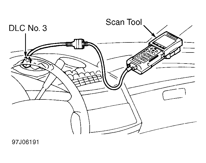 Courtesy of © TOYOTA, LICENSE AGREEMENT TMS1002
- Disconnect MAF sensor connector. Ensure ignition is on. Using DVOM, measure voltage between ground and terminal No. 1 (Black/Orange wire) at MAF wiring harness connector. See Fig 2. If voltage is 9-14 volts, go to next step. If voltage is not 9-14 volts, check for open circuit in wiring harness between EFI main relay and MAF sensor. See appropriate wiring diagram in WIRING DIAGRAMS
article. Repair wiring as necessary.
- Access ECM under driver's seat. Start engine. Backprobing ECM connector, measure voltage between ground and terminal No. 2 (Green/Red wire) at ECM E6 connector. See Fig 3. If voltage is 1.1-1.5 volts, replace ECM and retest.
- If voltage is not 1.1-1.5 volts, check for open or short circuit in wiring harness between MAF sensor and ECM. See appropriate wiring diagram in WIRING DIAGRAMS
article. Repair wiring as necessary. If wiring harness is okay, replace MAF sensor and retest.
- Access ECM under driver's seat. Turn ignition off. Using ohmmeter, backprobe ECM connector. Check continuity between ground and terminal No. 14 (Green/White wire) at ECM E6 connector. See Fig 3. If continuity does not exist, replace ECM and retest. If continuity exists, check for open circuit in wiring harness between MAF sensor and ECM. See appropriate wiring diagram in WIRING DIAGRAMS
article. Repair wiring as necessary. If wiring harness is okay, replace MAF sensor.
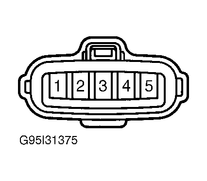 Courtesy of © TOYOTA, LICENSE AGREEMENT TMS1002
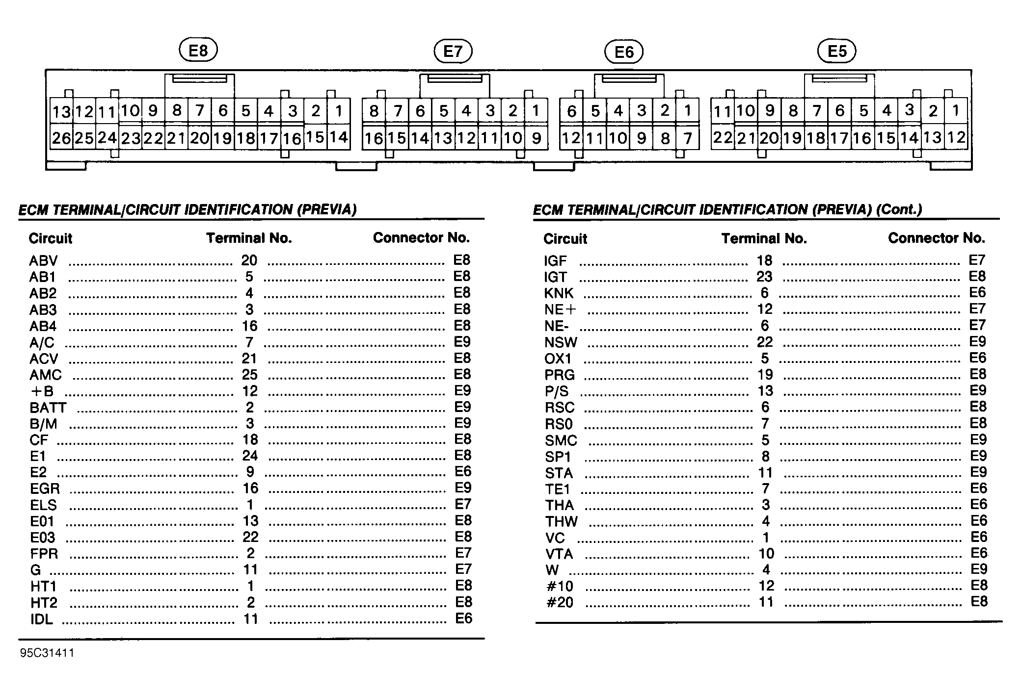 Courtesy of © TOYOTA, LICENSE AGREEMENT TMS1002