Diagnosis & Repair
- Check for spark at misfiring cylinder. See IGNITION CHECKS in BASIC TESTING
article. If spark is present, go to next step. If spark is not present, go to step 4).
- Check for open or short in IGF circuit between ECM and ignitor. Ignitor is located near left shock tower. See appropriate wiring diagram in WIRING DIAGRAMS
. Repair wiring as necessary. If circuit is okay, go to next step.
- Disconnect Black 10-pin ignitor connector. Access ECM behind glove box. Turn ignition on. Measure voltage between ground and terminal No. 12 (White/Red wire) at ECM E8 connector. See Figure. If voltage is 4.5-5.5 volts, replace ignitor. If voltage is not 4.5-5.5 volts, replace ECM and retest.
- Check for open or short in IGT1, IGT2 and IGT3 circuits between ECM and ignitor. See appropriate wiring diagram in WIRING DIAGRAMS
article. Repair wiring as necessary. If circuits are okay, go to next step.
- Access ECM behind glove box. Locate ECM E8 connector. See Figure. Backprobing ECM connector, measure voltage between ground and terminals No. 15 (Green/Red wire), No. 16 (Yellow/Red wire) and No. 24 (Blue/Black wire) at ECM E8 connector while cranking engine. If all readings are .1-4.5 volts, go to next step. If any reading is not .1-4.5 volts, replace ECM and retest.
- Disconnect Black 10-pin ignitor connector. Backprobing ECM connector, measure voltage between ground and terminals No. 15 (Green/Red wire), No. 16 (Yellow/Red wire) and No. 24 (Blue/Black wire) at ECM E8 connector while cranking engine. If all readings are .1-4.5 volts, go to next step. If any reading is not .1-4.5 volts, replace ECM and retest.
- Turn ignition on. Measure voltage between ground and terminal No. 9 (Black/Red wire) at ignitor wiring harness connector. See Fig 1. If voltage is 9-14 volts, go to next step. If voltage is not 9-14 volts, check and repair ignitor power source circuit. See appropriate wiring diagram in WIRING DIAGRAMS
article.
- Check for an open or short in wiring harness between ignition switch and ignition coil, and between ignition coil and ignitor. Repair wiring as necessary. If wiring is okay, go to next step.
- Check ignition coil. See IGNITION CHECKS in BASIC TESTING
article. Replace coil as necessary. If coil is okay, replace ignitor.
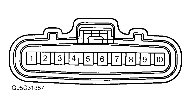 Courtesy of © TOYOTA, LICENSE AGREEMENT TMS1002