IG1 Power Source Circuit
- Ensure charging system is working properly. Repair as necessary. Turn ignition on. Measure voltage between ABS ECU connector terminals IG1 and GND. See Fig 1 or Fig 2
. Battery voltage should exist. If battery voltage does not exist, go to next step. If battery voltage exists, replace ABS ECU.
- Check resistance between ABS ECU connector terminal GND and body ground. Resistance should be one ohm or less. If resistance is not as specified, repair or replace wiring harness or connector as necessary. If resistance is as specified, check ECU-IG fuse, located in fuse box.
- If fuse is okay, check for open in wiring harness and connector between ABS ECU and battery. If fuse is not okay, check for short in all wiring harness components connected to ECU-IG fuse. See WIRING DIAGRAMS .
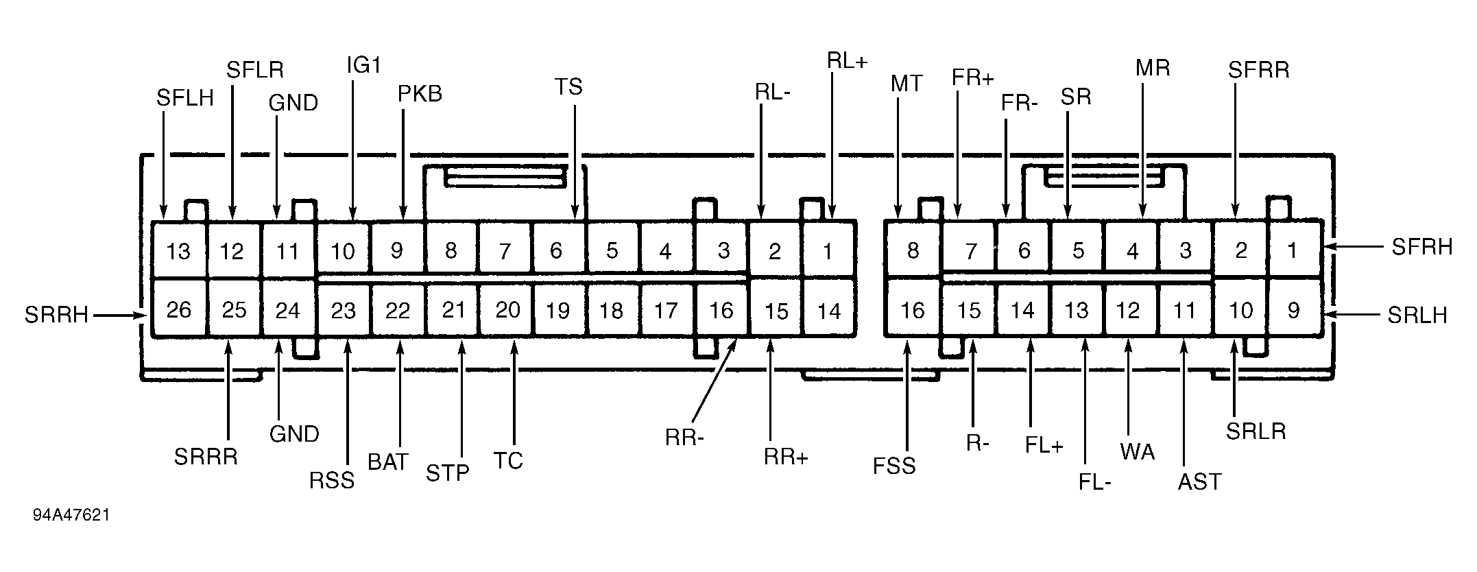 Courtesy of © TOYOTA, LICENSE AGREEMENT TMS1002
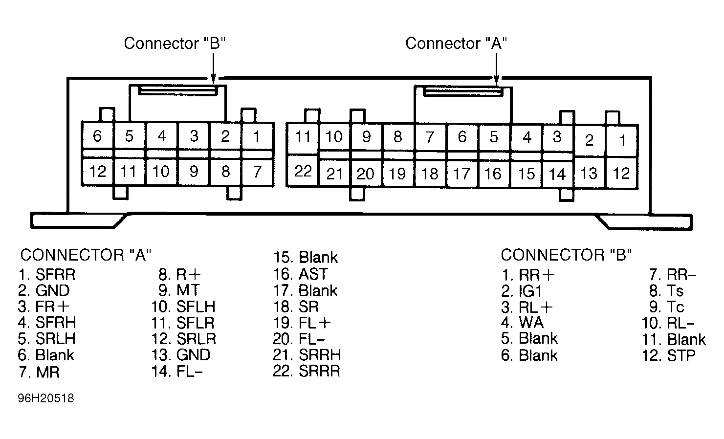 Courtesy of © TOYOTA, LICENSE AGREEMENT TMS1002