Diagnosis & Repair
- Turn ignition on. Using jumper wire, connect DLC1 terminals +B and FP. See Figure. Check if fuel pressure can be felt in hose to fuel filter. If pressure is felt, go to next step. If pressure cannot be felt, go to step 3).
- Check for open or short in +B and FP circuits between DLC1 and fuel pump ECU. Fuel pump ECU is back of left rear wheelwell, behind trim panel. See WIRING DIAGRAMS
article. Repair as needed. If circuits are okay, go to step 5).
- Ensure ignition is on. Using DVOM, measure voltage between DLC1 connector terminal +B and ground. If 9-14 volts is present, go to next step. If 9-14 volts is not present, inspect ECM power supply circuit and +B circuit between DLC1 connector and main relay. See wiring diagram in the WIRING DIAGRAMS
article. Repair as needed.
- Inspect FP circuit for open or short between DLC1 connector, fuel pump and ground. Repair as needed. If circuit is okay, replace fuel pump.
- Access fuel pump ECU. Fuel pump ECU is back of left rear wheelwell, behind trim panel. Disconnect harness connector. Check voltage between harness connector terminals E and FPC. See Fig 1. Turn ignition switch to START position. If voltage is 4.5-5.5 volts, replace fuel pump ECU. If voltage is NOT 4.5-5.5 volts, go to next step.
- Inspect FPC circuit between ECM and fuel pump ECU for open. See wiring diagram in the WIRING DIAGRAMS
article. Repair as needed. Inspect E circuit between fuel pump ECU and ground. Repair as needed. If both circuits are okay, go to next step.
- Inspect DI circuit between ECM and fuel pump ECU for open or short. See the WIRING DIAGRAMS
article. Repair as needed. If circuit is okay, replace ECM and retest.
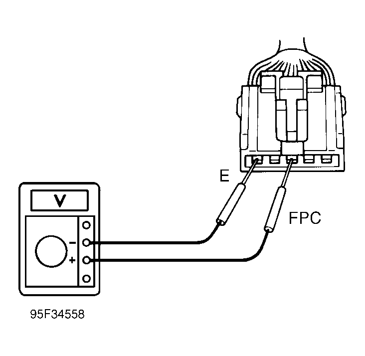 Courtesy of © TOYOTA, LICENSE AGREEMENT TMS1002