- Put the front subframe assembly with the powertrain table/subframe fixture under the vehicle for installation.
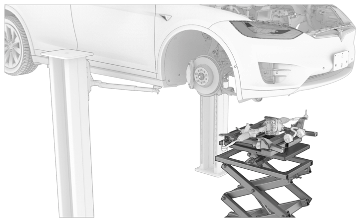 Courtesy of TESLA, INC. Courtesy of TESLA, INC.
|
- Slowly lift the front subframe assembly to access the power and ground connections for the steering rack, and then connect the electrical connectors (x2).
NOTE:
Adjust the powertrain table/subframe fixture as needed.
NOTE:
Make sure that an audible click is heard when the locking tabs for the electrical connectors are engaged.
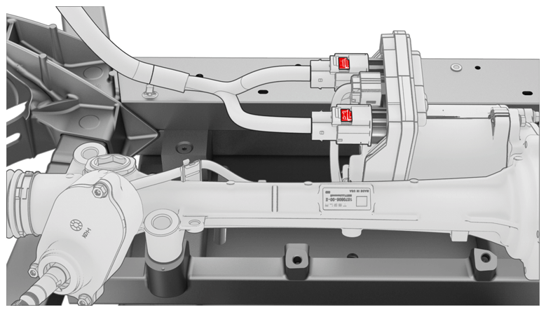 Courtesy of TESLA, INC. Courtesy of TESLA, INC.
|
- Raise the front subframe assembly into position to be installed.
NOTE:
Adjust the powertrain table/subframe fixture as needed.
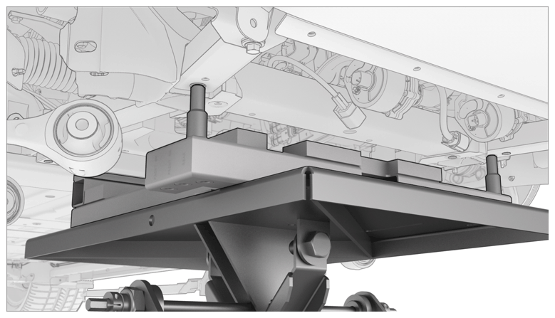 Courtesy of TESLA, INC. Courtesy of TESLA, INC.
|
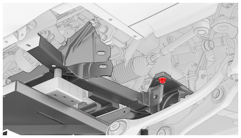
- Install the RH rear bolt that attaches the front subframe assembly to the body (torque 115 N.m). Repeat this step on the LH rear bolt.
NOTE:
RH side
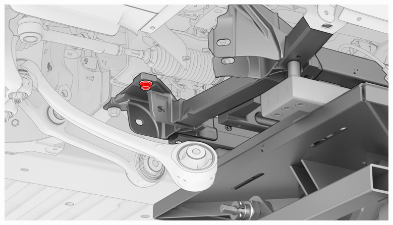 Courtesy of TESLA, INC. Courtesy of TESLA, INC.
|
NOTE:
LH side
 Courtesy of TESLA, INC. Courtesy of TESLA, INC.
|
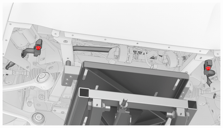
- Install the bolt that attaches the RH stabilizer bar mount to the body through the front subframe assembly (torque 80 N.m). Repeat this step on the LH stabilizer bar mount.
 Courtesy of TESLA, INC. Courtesy of TESLA, INC.
|
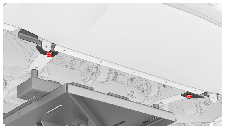
- Install the bolt that attaches the RH side condenser bracket to the front subframe assembly (torque 20 N.m). Repeat this step on the LH side condenser bracket.
 Courtesy of TESLA, INC. Courtesy of TESLA, INC.
|
- Lower the powertrain table, and then remove it from under the vehicle.
- Disconnect the shop air supply from the powertrain table.
- Put the coolant drain container under the LH front corner of the vehicle to catch any coolant during the next step.
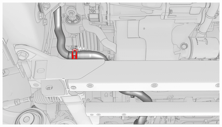
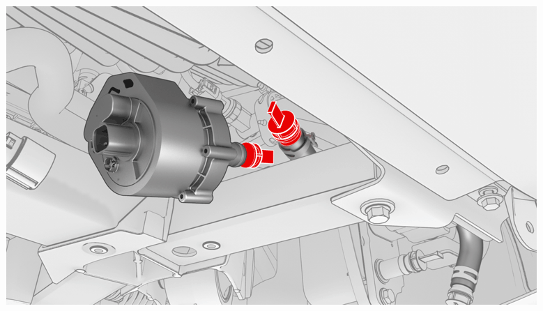
- Remove the plugs, and then connect the hose from the battery coolant heater to coolant pump 2 at the rear of the front subframe assembly.
NOTE:
The coolant drain container might need to be moved to properly catch any residual coolant.
 Courtesy of TESLA, INC. Courtesy of TESLA, INC.
|
- Remove the plugs, and then connect the chiller to the battery coolant pump 1 hose.
 Courtesy of TESLA, INC. Courtesy of TESLA, INC.
|
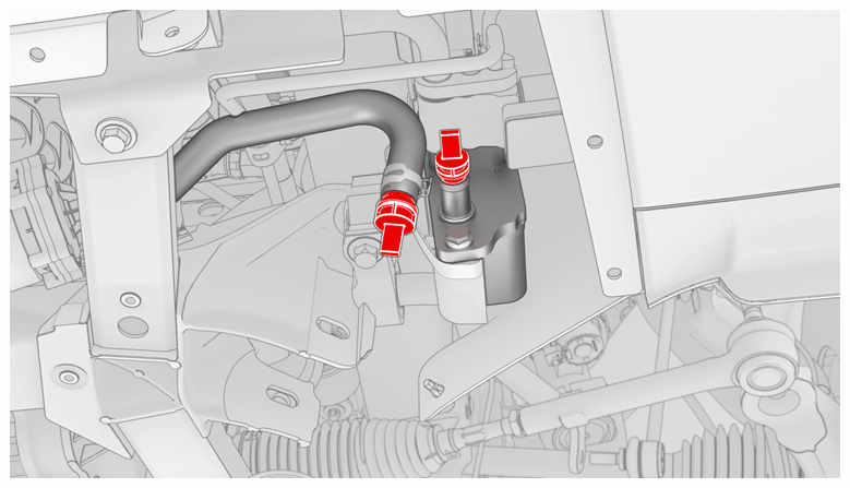
- Remove the plugs, and then connect the chiller to the battery coolant pump 1 hose.
 Courtesy of TESLA, INC. Courtesy of TESLA, INC.
|
- Remove the coolant drain container from under the vehicle.
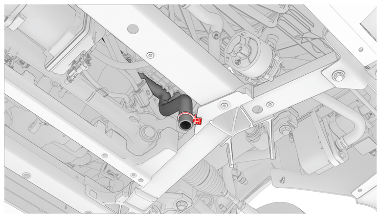
- Install the edge clip that attaches the windshield cowl drain to the front subframe assembly.
 Courtesy of TESLA, INC. Courtesy of TESLA, INC.
|
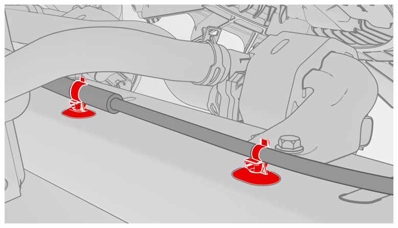
- Install the fir tree clips (x2) that attach the electrical harness to the front subframe assembly.
 Courtesy of TESLA, INC. Courtesy of TESLA, INC.
|
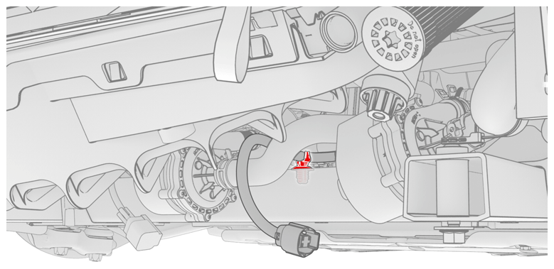
- Install the fir tree clip that attaches the battery pump 1 pigtail to the front subframe assembly.
 Courtesy of TESLA, INC. Courtesy of TESLA, INC.
|
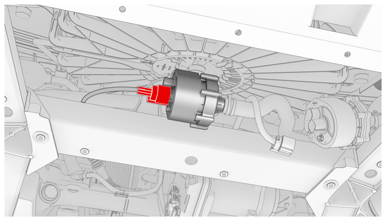
- Connect the battery pump 2 electrical connector.
 Courtesy of TESLA, INC. Courtesy of TESLA, INC.
|
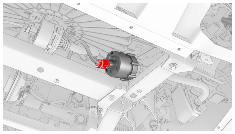
- Connect the batter pump 1 electrical connector.
 Courtesy of TESLA, INC. Courtesy of TESLA, INC.
|
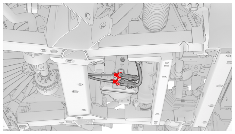
- Connect the logic connectors (x2) for the steering rack.
NOTE:
Engage the gray lock after each electrical connector is fully seated.
 Courtesy of TESLA, INC. Courtesy of TESLA, INC.
|
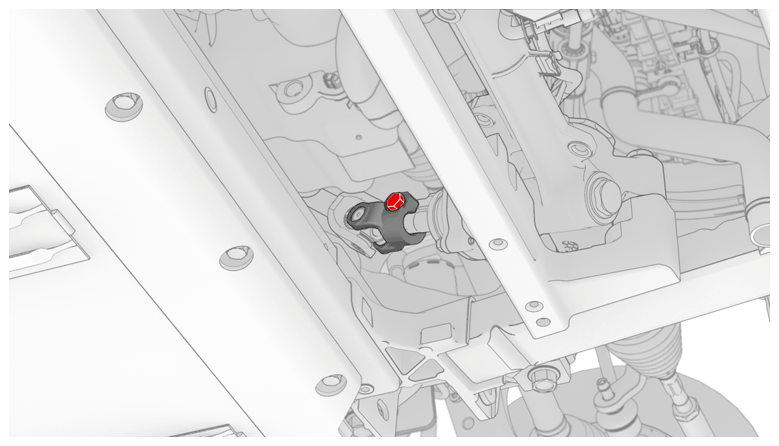
- Slide the lower i-shaft onto the steering rack, and then install the bolt that attaches the lower i-shaft to the steering rack (torque 30 N.m).
 Courtesy of TESLA, INC. Courtesy of TESLA, INC.
|
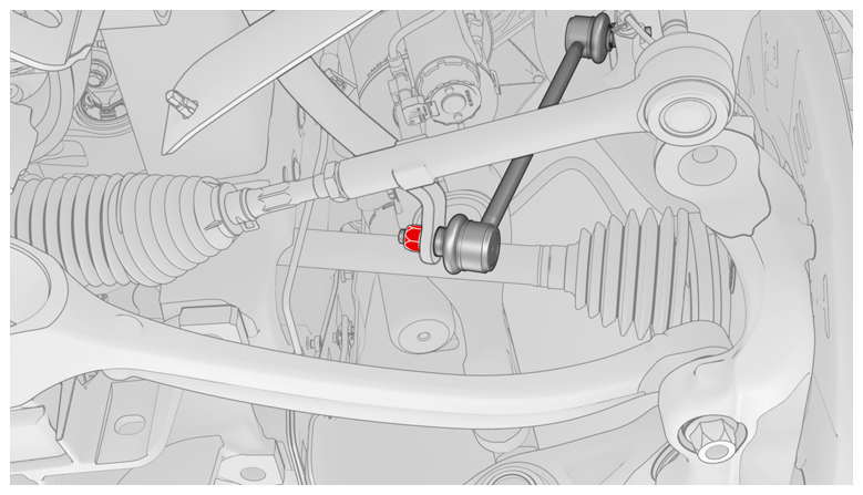
- Install a new nut that attaches the RH stabilizer bar to the stabilizer bar end link (torque 70 N.m). Repeat this step on the LH stabilizer bar.
NOTE:
LH shown, RH similar
 Courtesy of TESLA, INC. Courtesy of TESLA, INC.
|
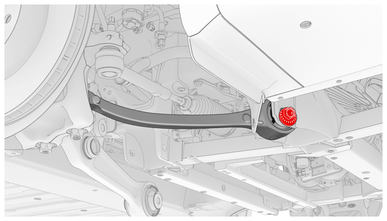
- Move the RH front fore link into the front subframe assembly, properly align the paint marks, and then hand-tighten the bolt that attaches the RH front lower fore link to the subframe.
NOTE:
The bolt will be fully tightened during wheel alignment later in this procedure (torque specification for the bolt is 130 N.m).
 Courtesy of TESLA, INC. Courtesy of TESLA, INC.
|
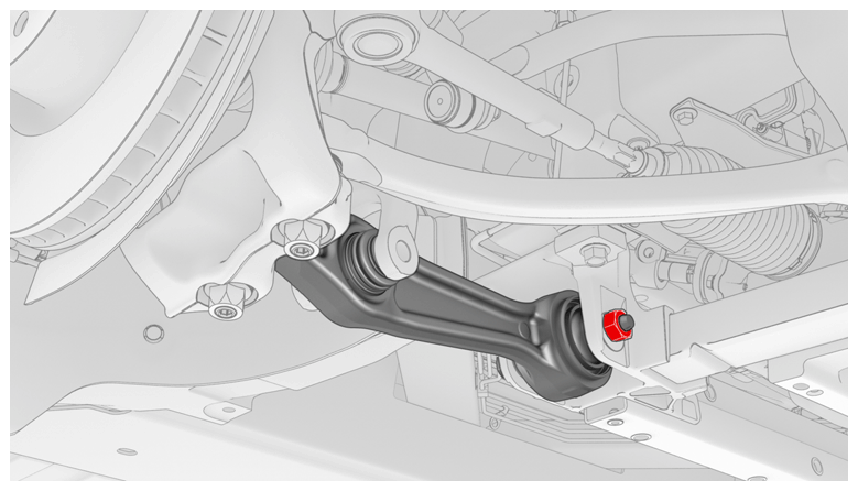
- Move the RH front lower aft link into position on the front subframe assembly, and then hand-tighten the bolt.
NOTE:
Make sure that the bolt is installed with the bolt head facing the front of the vehicle.
NOTE:
The bolt will be fully tightened during wheel alignment later in this procedure (torque specification for the bolt is 130 N.m).
 Courtesy of TESLA, INC. Courtesy of TESLA, INC.
|
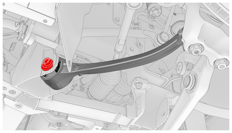
- Move the LH front lower fore link into the front subframe assembly, properly align the paint marks, and then hand-tighten the bolt that attaches the link to the subframe.
NOTE:
The bolt will be fully tightened during wheel alignment later in this procedure (torque specification for the bolt is 130 N.m).
 Courtesy of TESLA, INC. Courtesy of TESLA, INC.
|
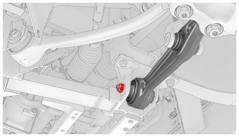
- Move the LH front lower aft link into position on the front subframe assembly, and then hand-tighten the bolt that attaches the link to the subframe.
NOTE:
Make sure that the bolt is installed with the bolt head facing the front of the vehicle.
NOTE:
The bolt will be fully tightened during wheel alignment later in this procedure (torque specification for the bolt is 130 N.m).
 Courtesy of TESLA, INC. Courtesy of TESLA, INC.
|
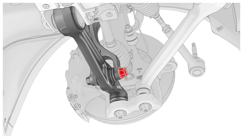
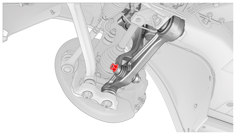
- Install the bolt that attaches the LH front strut to the front lower aft link. Repeat this step on the RH front strut.
NOTE:
Torque the bolts at ride height when the vehicle is on the alignment rack later in this procedure.
NOTE:
LH side
 Courtesy of TESLA, INC. Courtesy of TESLA, INC.
|
NOTE:
RH side
 Courtesy of TESLA, INC. Courtesy of TESLA, INC.
|
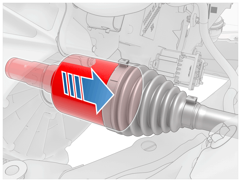
- Pull on the LH and RH front inner halfshaft cups to confirm that the circlip is locked into place. If the halfshaft detaches from the drive unit then reinstall the halfshaft and then test that it is fully seated.
CAUTION:
If reinstalling the halfshaft to the drive unit:
- Take care not to damage or displace the oil seals.
- Make sure that the opening of the snap rings are facing towards the bottom of the drive unit.
- Carefully push the halfshaft into the drive unit until there is an audible "click" from the halfshaft stub contacting the pinion shaft.
- There will be a slight pulling sensation on the halfshaft as the halfshaft circlip locks into place.
- Pull on the inner halfshaft cup to confirm that the circlip is locked into place. If the halfshaft detaches from the drive unit then reinstall the halfshaft and then test that it is fully seated.
 Courtesy of TESLA, INC. Courtesy of TESLA, INC.
|
- Install the front subframe skid bar. See SKID BAR - FRONT SUBFRAME (REMOVE AND REPLACE) .
- Install the front skidplate. See SKIDPLATE - FRONT (REMOVE AND REPLACE) .
- Install the HV battery assembly. See HV BATTERY (AWD) (REMOVE AND INSTALL)
.
- Install the front aero shield panel. See PANEL - AERO SHIELD - FRONT (REMOVE AND REPLACE)
.
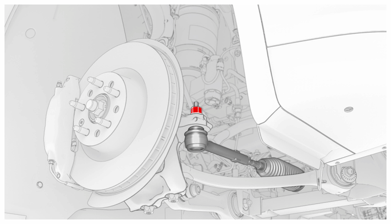
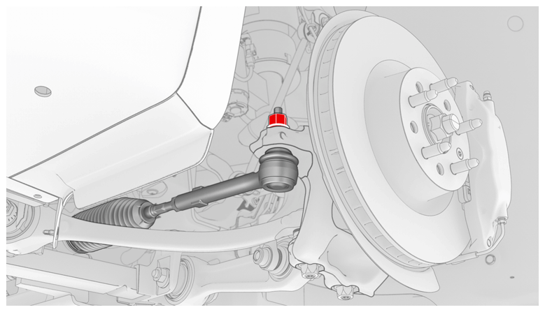
- Install the LH tie rod end into the knuckle, and then install a new LH nyloc nut that attaches the tie rod end to the steering knuckle (torque 103 N.m). Repeat this step on the RH tie rod end.
NOTE:
RH tie rod
 Courtesy of TESLA, INC. Courtesy of TESLA, INC.
|
NOTE:
LH tie rod
 Courtesy of TESLA, INC. Courtesy of TESLA, INC.
|
- Install the LH and RH front wheels. See WHEEL (REMOVE AND INSTALL)
.
- Reconnect 12V power. See DISCONNECT 12V POWER
.
- Connect a laptop with Toolbox to the vehicle.
- In Toolbox 3, click the Actions
tab, type "Coolant air purge" into the search field, click PROC_THC_X_COOLANT-AIR-PURGE
, click Run
, and allow the routine to complete.
- Top off the coolant reservoir, if necessary.
- Disconnect the laptop from the vehicle and reinstall the storage cubby.
- Install the HEPA filter. See FILTER - HEPA (REMOVE AND REPLACE)
.
- Install the underhood storage unit. See UNDERHOOD STORAGE UNIT (REMOVE AND REPLACE)
.
- Install the underhood storage carpet. See CARPET - UNDERHOOD STORAGE (REMOVE AND INSTALL)
.
- Reconnect the electrical connectors for the LH and RH underhood storage area lights. See LIGHT - UNDERHOOD STORAGE AREA - LH (REMOVE AND REPLACE)
.
- Install the front underhood apron. See ASSEMBLY - UNDERHOOD APRON - FRONT (REMOVE AND REPLACE)
.
- Install the LH and RH underhood aprons. See UNDERHOOD APRON - LH (REMOVE AND REPLACE)
.
- Install the rear center underhood apron. See UNDERHOOD APRON - CENTER - REAR (REMOVE AND REPLACE)
.
- Close the hood.
- Touch and hold the CALIBRATE
button on the Model X touchscreen until the rear doors have been fully calibrated, close completely, and the message "CALIBRATION COMPLETE" is displayed.
- Raise the vehicle on a 4 post lift. See RAISE VEHICLE - 4 POST LIFT
.
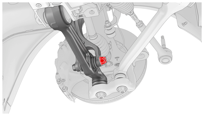
- Fasten the bolt that attaches the LH front strut to the front lower aft link (torque 140 N.m). Repeat this step on the RH front strut.
NOTE:
LH side
 Courtesy of TESLA, INC. Courtesy of TESLA, INC.
|
NOTE:
RH side
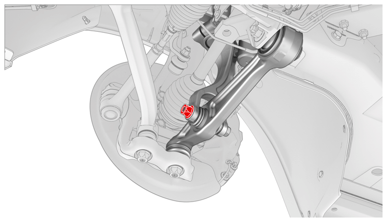 Courtesy of TESLA, INC. Courtesy of TESLA, INC.
|
- Refer to the Alignment Requirement tables to determine if an alignment check (AC) or full adjustment (FA) is necessary. See ALIGNMENT REQUIREMENT - SUSPENSION
.
NOTE:
Make sure that the front fore links, front lower fore links, and the front lower aft links are tightened to specifications during the four wheel alignment check and adjust procedure.
- Install the mid aero shield panel. See PANEL - AERO SHIELD - MID (REMOVE AND REPLACE)
.
- Lower the vehicle.
- Remove the brake pedal depressor, the steering wheel level, and the steering wheel holder from the vehicle.
- Remove the wheel chocks, and then remove the vehicle from the 4-post lift.
- Perform a vehicle test drive.