Camshaft Position Sensor (Method With Oscilloscope)
- Prepare an oscilloscope.
- Remove the glove box lid assembly. Refer to GLOVE BOX
.
- Connect the probe to ECM connector.
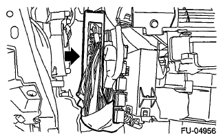 Courtesy of SUBARU OF AMERICA, INC.
- Intake camshaft position sensor
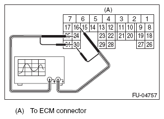 Courtesy of SUBARU OF AMERICA, INC.
- Exhaust camshaft position sensor
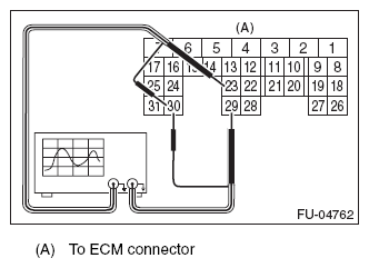 Courtesy of SUBARU OF AMERICA, INC.
| Camshaft position sensor |
Terminal No. |
Probe |
| Intake |
RH |
24 |
+ |
| LH |
16 |
+ |
| Exhaust |
RH |
23 |
+ |
| LH |
29 |
+ |
| RH and LH |
30 |
- |
- Start the engine and let it idle.
- Check that the pattern is the same as the waveform and voltage shown below.
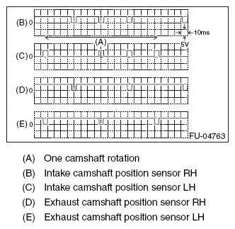 Courtesy of SUBARU OF AMERICA, INC.
- After inspection, install the related parts in the reverse order of removal.