Forester, Impreza 2.5L & Outback Sport
- Turn ignition on and listen for sound of fuel pump operation. If fuel pump operates for 2 seconds when ignition is turned on, check fuel injector circuit. See FUEL INJECTOR CIRCUIT
. If fuel pump does not operate for 2 seconds when ignition is turned on, go to next step.
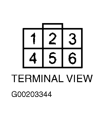
- Turn ignition off. Remove fuel pump access hole cover located under right rear side of luggage compartment floor (wagon) or under right side of rear seat (sedan). Disconnect 6-pin electrical harness connector from fuel pump. Using a DVOM, measure resistance of Black wire between a good chassis ground point and harness side of fuel pump 6-pin electrical harness connector terminal No. 4. See Fig 1
. If resistance is less than 5 ohms, go to next step. If resistance is not less than 5 ohms, repair open circuit in harness between fuel pump connector and chassis ground point located at right rear side on Forester or under right front seat on Impreza 2.5L and Outback Sport. Also check contact of terminals in connectors between fuel pump and chassis ground point. See ENGINE PERFORMANCE in SYSTEM WIRING DIAGRAMS article in ELECTRICAL.
- Turn ignition on. Using a DVOM, measure voltage between harness side of fuel pump 6-pin electrical harness connector terminal No. 1 (Black/Red wire) and good chassis ground point. See Fig 1
. If voltage is not greater than 10 volts, go to next step. If voltage is greater than 10 volts, replace fuel pump.
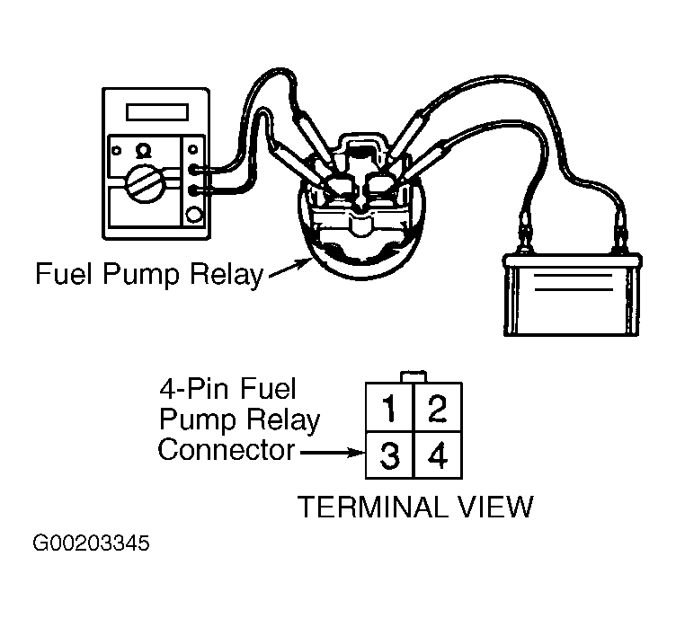
- Turn ignition off. Disconnect Green 4-pin electrical harness connector from fuel pump relay and leave fuel pump connector disconnected. Using a DVOM, measure resistance between harness side of fuel pump 6-pin electrical harness connector terminal No. 1 (Black/Red wire) and harness side of fuel pump relay 4-pin electrical harness connector terminal No. 4 (Black/Yellow wire). See Fig 1
and Fig 2
. If resistance is less than one ohm, go to next step. If resistance is not less than one ohm, repair open circuit in harness between fuel pump and fuel pump relay. See ENGINE PERFORMANCE in SYSTEM WIRING DIAGRAMS article in ELECTRICAL.
- Turn ignition off and leave fuel pump and fuel pump relay connectors disconnected. Using a DVOM, measure resistance of Black/Red wire between harness side of fuel pump 6-pin electrical harness connector terminal No. 1 and good chassis ground point. See Fig 1
. If resistance is greater than one megohm, go to next step. If resistance is not greater than one megohm, repair short circuit in harness between fuel pump and fuel pump relay. See ENGINE PERFORMANCE in SYSTEM WIRING DIAGRAMS article in ELECTRICAL.
- Remove fuel pump relay. Using jumper wires, connect battery voltage to fuel pump relay terminal No. 1 and ground terminal No. 3. Measure resistance between fuel pump relay terminals No. 2 and 4. See Fig 2
. If resistance is less than 10 ohms, go to next step. If resistance is not less than 10 ohms, replace fuel pump relay.
- Turn ignition off. Locate ECM and disconnect 35-pin electrical harness connector B134. Using a DVOM, measure resistance of Violet/White wire between harness side of ECM 35-pin electrical harness connector B134 terminal No. 16 (Blue/Red wire on Forester) and harness side of fuel pump relay 4-pin electrical harness connector terminal No. 3. See Figure
and Fig 2
. If resistance is less than one ohm, go to next step. If resistance is not less than one ohm, repair open circuit in harness between ECM and fuel pump relay. See ENGINE PERFORMANCE in SYSTEM WIRING DIAGRAMS article in ELECTRICAL.
- Check for poor contact of terminals in connectors between ECM and fuel pump relay. If poor contact exists in any connector, repair as required. See ENGINE PERFORMANCE in SYSTEM WIRING DIAGRAMS article in ELECTRICAL. If poor contact does not exist, check fuel injector circuit. See FUEL INJECTOR CIRCUIT
.
 Courtesy of SUBARU OF AMERICA, INC.
 Courtesy of SUBARU OF AMERICA, INC.