Mike's Workshop Manuals
: Service manuals for every vehicle
Home
>>
Saturn
>>
2008
>>
Aura Green Line
>>
Repair and Diagnosis
>>
Brakes
>>
Anti-Lock Brake System, Traction Control System & Stability Control System
>>
Schematic and Routing Diagrams
>>
Antilock Brake System Schematics
Antilock Brake System Schematics
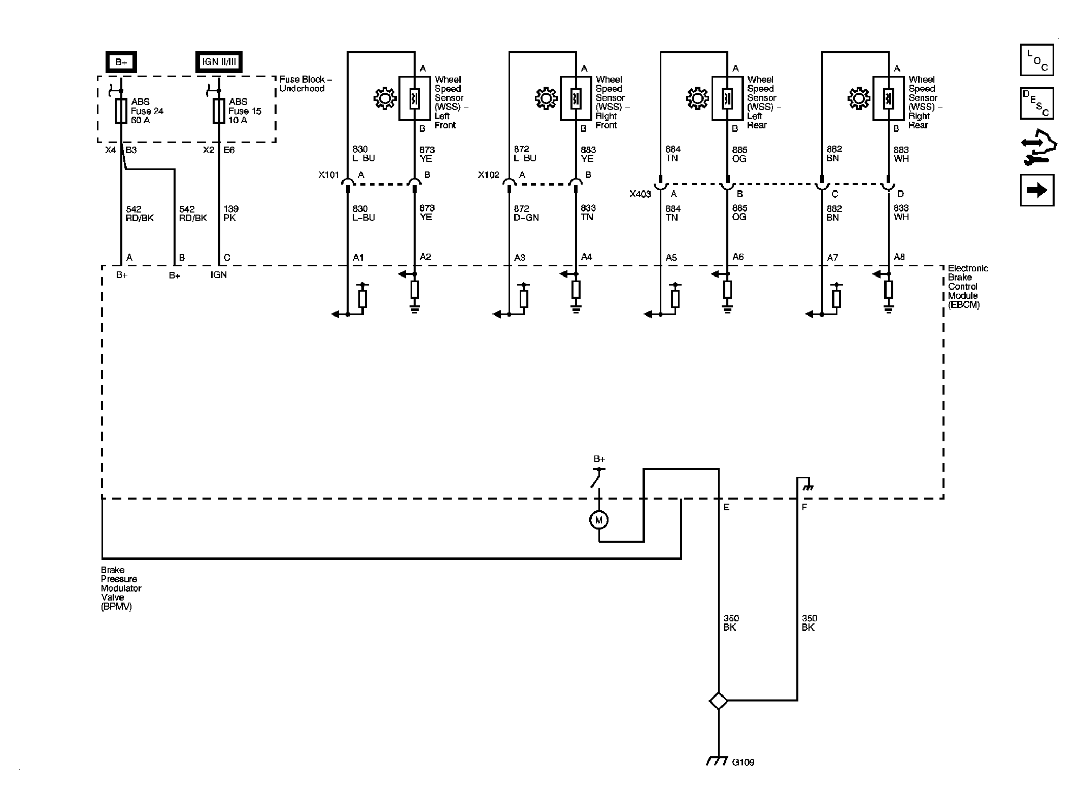
Fig 1: Power, Ground, Brake Pressure Modulator Valve and Wheel Speed Sensors Schematic
Courtesy of GENERAL MOTORS CORP.
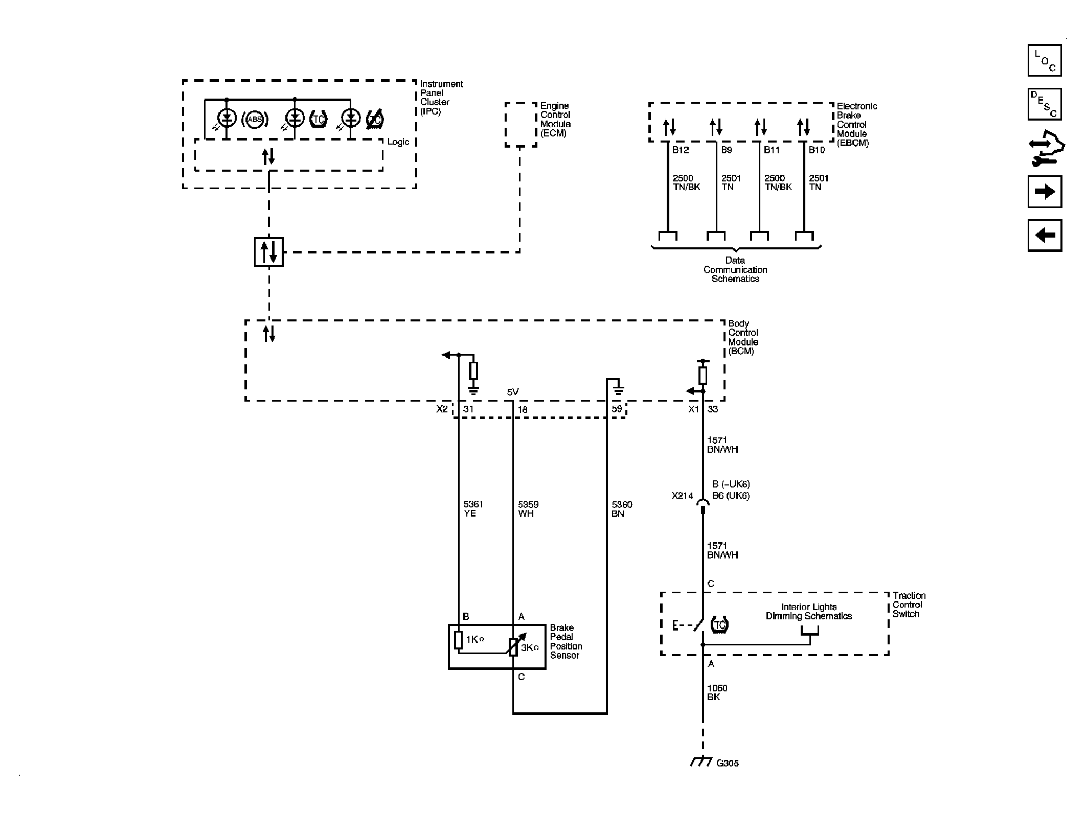
Fig 2: Brake Pedal Position Sensor, Data Link Communications and Traction Controls Switch Schematic
Courtesy of GENERAL MOTORS CORP.
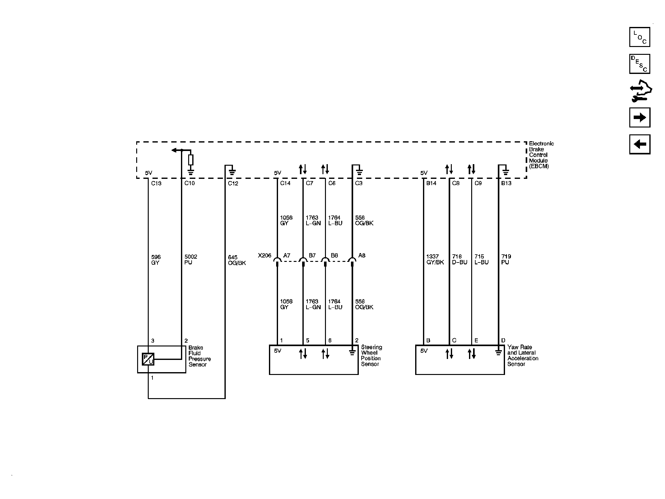
Fig 3: Brake Pedal Position Sensor, Steering Wheel Position Sensor and Yaw Rate and Lateral Acceleration Sensor (FX3) Schematic
Courtesy of GENERAL MOTORS CORP.
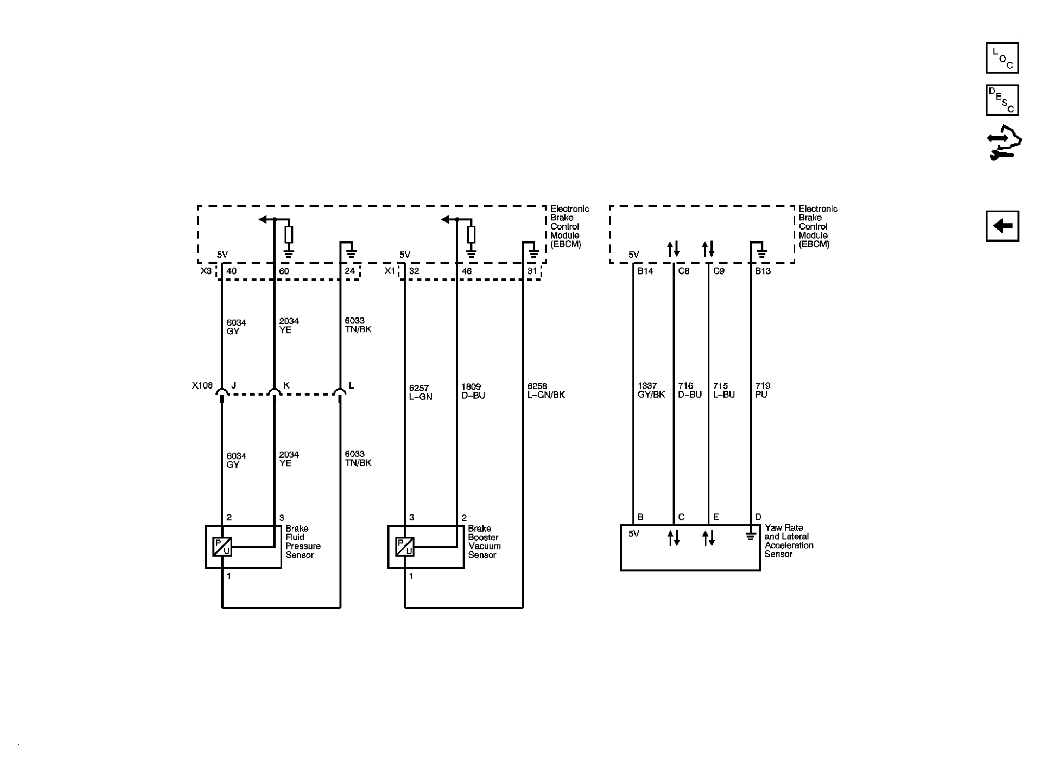
Fig 4: Brake Booster Vacuum Sensor, Brake Fluid Pressure Sensor and Yaw Rate and Lateral Acceleration Sensor (LAT) Schematic
Courtesy of GENERAL MOTORS CORP.
 Courtesy of GENERAL MOTORS CORP.
 Courtesy of GENERAL MOTORS CORP.
 Courtesy of GENERAL MOTORS CORP.
 Courtesy of GENERAL MOTORS CORP.