Disassembly Procedure
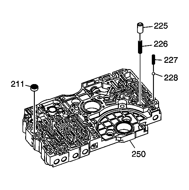 Courtesy of GENERAL MOTORS CORP.
- If not removed during the control valve body removal, remove the following components:
- The transmission fluid cooler check ball (228) and spring (227)
- The torque converter check valve (225) and return spring (226)
- Remove the transmission fluid servo valve body filter (211)
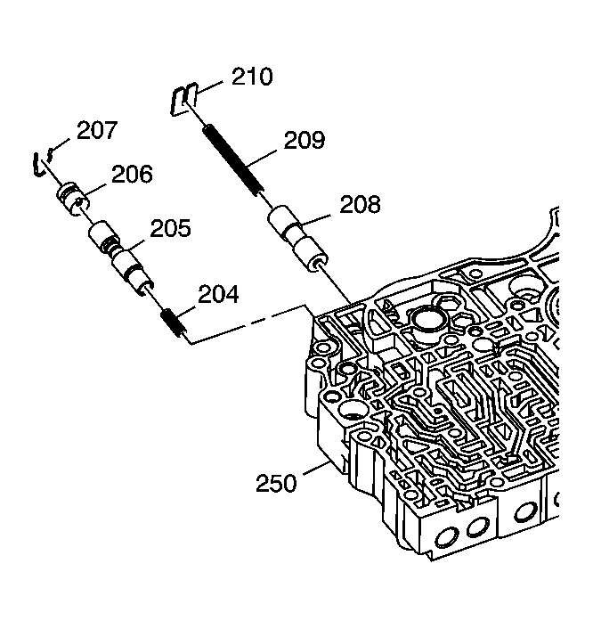 Courtesy of GENERAL MOTORS CORP.
- Remove the following components from the control valve body assembly (250):
- The bore plug retainer clip (207)
- The bore plug (206)
- The CPC valve (205)
- The CPC valve return spring (204)
- The valve spring retainer (210)
- The shift valve E return spring (209)
- The shift valve E (208)
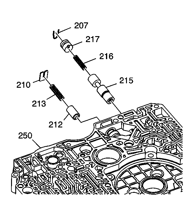 Courtesy of GENERAL MOTORS CORP.
- Remove the following components from the control valve body assembly (250):
- The valve spring retainer plate (210)
- The relief valve return spring (213)
- The relief valve (212)
- The bore plug retainer clip (207)
- The bore plug (217)
- The lubrication control valve return spring (216)
- The lubrication control valve (215)
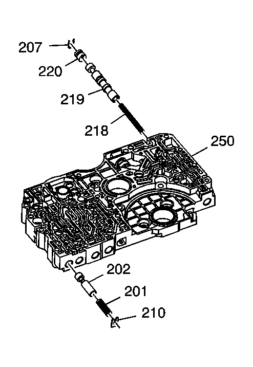 Courtesy of GENERAL MOTORS CORP.
- Remove the following components from the control valve body assembly (250):
- The bore plug retainer clip (207)
- The bore plug (220)
- The lock-up shift valve (219)
- The lock-up shift valve return spring (218)
- The valve spring retainer (210)
- The modulator valve return spring (201)
- The modulator valve (202)
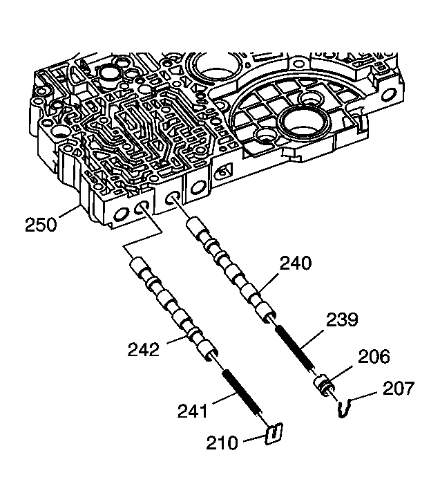 Courtesy of GENERAL MOTORS CORP.
- Remove the following components from the main control valve body assembly (250):
- The valve body spring retainer (210)
- The shift valve A return spring (241)
- The shift valve A (242)
- The bore plug retainer clip (207)
- The bore plug (206)
- The shift valve B return spring (239)
- The shift valve B (240)
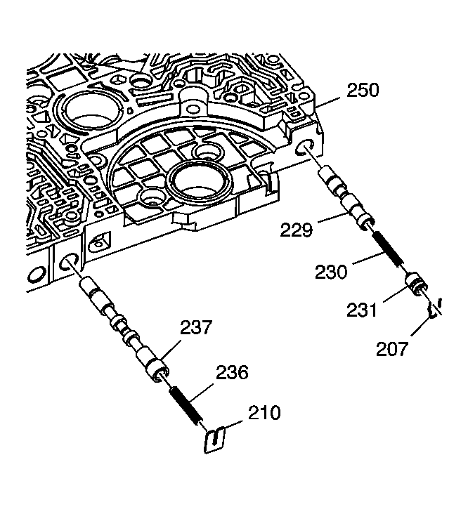 Courtesy of GENERAL MOTORS CORP.
- Remove the following components from the control valve body assembly (250):
- The valve body spring retainer (210)
- The shift valve D return spring (236)
- The shift valve D (237)
- The bore plug retainer clip (207)
- The bore plug (231)
- The lock-up timing valve return spring (230)
- The lock-up timing valve (229)