Instrument Panel Assembly Replacement
WARNING: This page is about a different car, the 2007 Pontiac Montana SV6, 2007 Chevrolet Uplander, and 2007 Buick Terraza. However, it is still accessible from the selected car via links, so may be relevant.
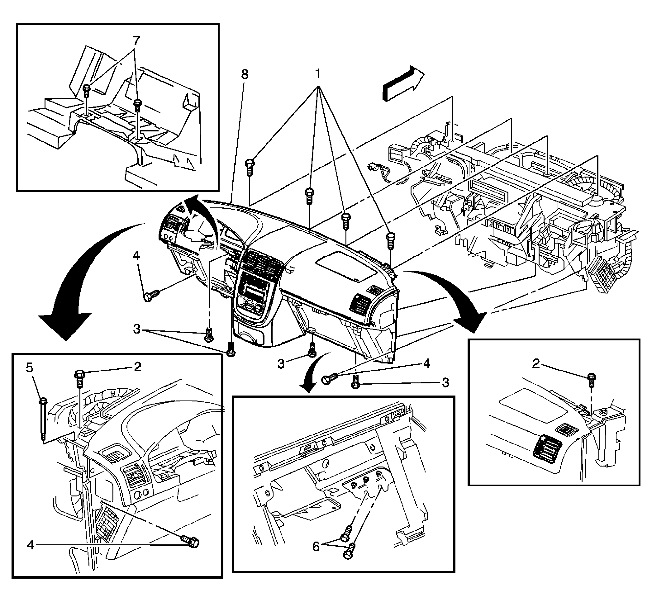 Courtesy of GENERAL MOTORS CORP.
 Instrument Panel Assembly Replacement
| Callout |
Component Name |
|
Fastener Tightening Specifications:
Refer to Fastener Tightening Specifications . |
|
Preliminary Procedures
- Disable the SIR. Refer to SIR Disabling and Enabling
.
- Disconnect the negative battery cable. Refer to Battery Negative Cable Disconnection and Connection
.
- Remove the instrument panel (I/P) insulators.
- Remove the I/P compartment assembly.
- Remove the I/P driver knee bolster assembly.
- Remove the I/P accessory trim plate.
- Remove the HVAC control module. Refer to HVAC Control Module Replacement
.
- Remove the radio. Refer to Radio Replacement
.
- Remove the driver information center.
- Remove the I/P cluster trim plate.
- Remove the I/P cluster.
- Remove the I/P lower trim molding.
- Remove the I/P steering column opening moldings.
- Remove the windshield pillar garnish moldings. Refer to Windshield Pillar Garnish Molding Replacement
.
- Remove the I/P upper trim pad.
- Remove the steering column assembly. Refer to Steering Column Replacement
.
- Remove the front floor console assembly.
- Remove the front floor console reinforcement.
- Remove the front floor console bracket.
- Remove the inflatable restraint I/P module. Refer to Inflatable Restraint Instrument Panel Module Replacement
.
- Remove the hood release handle. Refer to Hood Latch Release Handle Replacement
.
- Remove the screws for the data link connector. Refer to Data Link Connector Replacement
.
- Remove the carrier cover.
- Remove the lower extension panel.
|
| 1 |
Screw, I/P Carrier Trim Cover (Qty: 4) Tighten:
2 N.m (18 lb in)
|
| 2 |
Bolt, I/P Carrier (Qty: 2) Tighten:
10 N.m (89 lb in)
|
| 3 |
Screw, I/P Carrier (Qty: 4) Tighten:
4 N.m (25 lb in)
|
| 4 |
Screw, I/P Carrier (Qty: 2) Tighten:
4 N.m (25 lb in)
|
| 5 |
Bolt, I/P Carrier Pivot (Qty: 2) Tighten:
25 N.m (18 lb ft)
|
| 6 |
Screw, Passenger Air Bag Module (Qty: 2) Tighten:
4 N.m (25 lb in)
|
| 7 |
Screw, I/P Carrier (Qty: 2) Tighten:
4 N.m (25 lb in)
|
| 8 |
Panel Assembly, I/P
Tip:
- Lift up from the bottom of the I/P in order to release the top retainers.
- Remove the I/P wiring harness retainers that are attached to the I/P assembly.
- Remove the I/P panel assembly from the vehicle.
|