Fault Isolation Procedure
- Checking the sensor's grounding:
- Unplug the connector: Manifold absolute pressure sensor (431).
- Connect Test Lamp (86 1 857) to B+ and pin 4 of the female connector.
- Jiggle the leads and in-line connectors at several places and in different directions to reveal intermittent breaks and short circuits in the wiring harness. Observe the multimeter, test lamp or diagnostic tool while doing this.
If the test lamp illuminates, go to step 3, otherwise go to next step.
- Rectifying the lead: One of the leads from pins 22 and 70 of the control module to pin 4 of the female connector is faulty. (The leads from pins 22 and 70 of the control module are connected together internally in the throttle body.) Rectify the fault and go to step 9.
- Checking the sensor's power supply:
- Turn the ignition switch to the ON position.
- Take a voltage reading: (2,4) Manifold absolute pressure sensor.
- Jiggle the leads and in-line connectors at several places and in different directions to reveal intermittent breaks and short circuits in the wiring harness. Observe the multimeter, test lamp or diagnostic tool while doing this.
If the reading shows 4.9-5.1 volts, go to step 5, otherwise go to next step.
- Rectifying the lead: The lead from pins 69 and 46 of the control module to pin 4 of the female connector is faulty. (The leads from pins 69 and 46 of the control module are connected together internally in the throttle body.) Rectify the fault and go to step 9.
- Checking the control module's sensor input:
- Contact ECM.
- Read value: Manifold Absolute Pressure.
- Jiggle the leads and in-line connectors at several places and in different directions to reveal intermittent breaks and short circuits in the wiring harness. Observe the multimeter, test lamp or diagnostic tool while doing this.
If the reading shows zero kPa, go to step 7, otherwise go to next step.
- Rectifying the lead: The lead from pin 3 of the female connector to pin 11 of the control module is faulty. Rectify the fault and go to step 9.
- Checking the control module's sensor input (continued):
- Connect a jumper lead between pins 2 and 3 of the female connector.
- Read value: Manifold Absolute Pressure.
- Jiggle the leads and in-line connectors at several places and in different directions to reveal intermittent breaks and short circuits in the wiring harness. Observe the multimeter, test lamp or diagnostic tool while doing this.
On 4-Cyl models, if the reading shows 2.5 kPa, go to next next step, otherwise go to step 6. On V6 models, if the reading shows 250 kPa, go to next step, otherwise go to step 6.
- Changing components: Change the manifold absolute pressure sensor. When finished, go to next step.
- Checking the DTC:
- Put the ignition in the OFF position and wait for 5 seconds.
- Start the engine and rev it up to 4000 RPM.
- Release the accelerator pedal and wait for 1 minute.
- Obtain readouts of DTCs.
If the trouble code has recurred, the ECM is at fault and must be replaced. If the code is no longer present, the steps taken to rectify the fault were correct. Clear the DTCs from all systems.
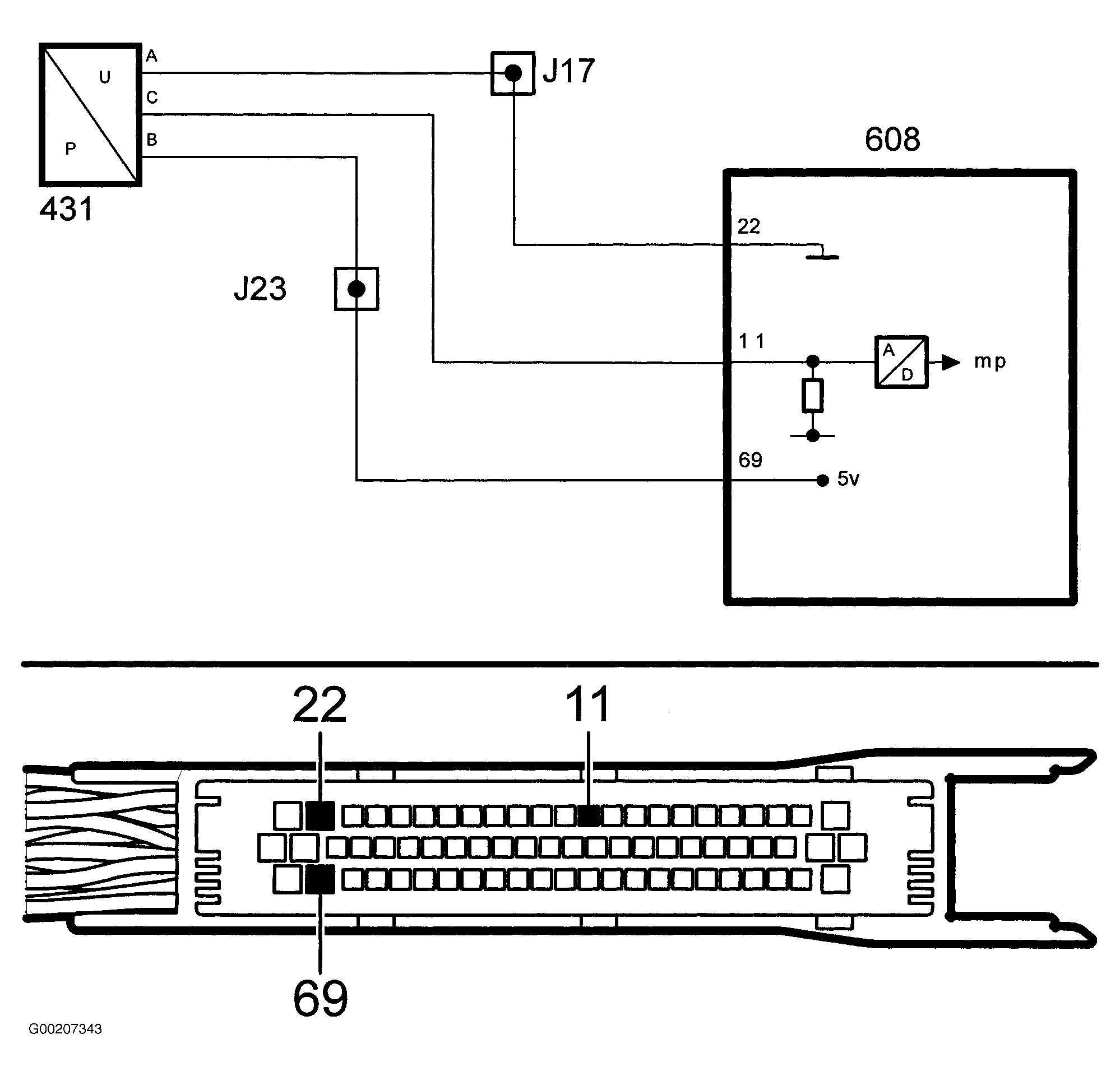 Courtesy of SAAB-SCANIA OF AMERICA, INC.