DTC U1500: Inter-Device Dedicated Bus Malfunction: Testing
- If cellular communications diagnostic system check has been performed, go to next step. If cellular communications diagnostic system check has not been performed, go to CELLULAR COMMUNICATION DIAGNOSTIC SYSTEM CHECK under SELF-DIAGNOSTIC SYSTEM.
- Turn ignition switch to OFF position. Disconnect Vehicle Communication Unit (VCU) 25-pin harness connector. VCU is located under instrument panel, left of blower motor. Turn ignition switch to RUN position. Using DVOM measure voltage between ground and VCU harness connector terminal No. 18 (Tan Black wire). See Fig 1. If approximately .2 volts exist, go to next step. If approximately .2 volts does not exist, go to step 5.
- Using DVOM measure voltage between ground and VCU harness connector terminal No. 12 (Dark Blue/White wire). If 5 volts exist, go to next step. If 5 volts does not exist, go to step 6.
- Using DVOM measure voltage between ground and VCU harness connector terminal No. 4 (Orange wire). If battery voltage exists, go to step 8. If battery voltage does not exist, go to step 7.
- Check for short to ground in Tan Black wire between VCU harness connector terminal No. 18 and Vehicle Interface Unit (VIU) harness connector C1 terminal B11. See Fig 1 and Fig 2
. If problem is found, repair as necessary and go to step 12. If no problem is found, go to step 9.
- Check for an open or short to voltage in Tan Black wire between VCU harness connector terminal No. 18 and VIU harness connector C1 terminal B11. See Fig 1 and Fig 2
. If problem is found, repair as necessary and go to step 12. If no problem is found, go to step 9.
- Check for short to voltage in Orange wire between VCU harness connector terminal No. 4 and VIU harness connector C1 terminal A16. See Fig 1 and Fig 2
. If problem is found, repair as necessary and go to step 12. If no problem is found, go to step 9.
- Check for poor, loose or corroded terminals in VCU harness connector. If problem is found, repair as necessary and go to step 12. If no problem is found, go to step 10.
- Check for poor, loose or corroded terminals in VIU harness connector. If problem is found, repair as necessary and go to step 12. If no problem is found, go to step 11.
- Replace VCU. See VEHICLE COMMUNICATIONS UNIT under REMOVAL & INSTALLATION.
- Replace VIU. See VEHICLE INTERFACE UNIT under REMOVAL & INSTALLATION.
- Using scan tool clear DTCs. Operate vehicle within conditions for code enable criteria. If DTC does not reset, testing is complete. If DTC resets, go to step 2.
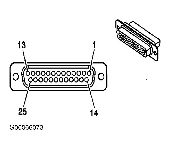 Courtesy of GENERAL MOTORS CORP.
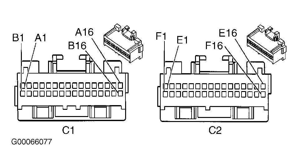 Courtesy of GENERAL MOTORS CORP.