Diagnostic Procedure (Frontier 2.4L)
- Disconnect fuel pump assembly harness connector located on top of fuel tank. Measure voltage between ground and fuel pump assembly harness connector terminal No. 1 (Orange/Black wire). See Figure
. If voltage is about 5 volts, go to step 3
. If voltage is not about 5 volts, go to next step.
- Check the following:
- Check for poor connection at White, 18-pin connector C1, terminal No. 10 (Orange/Black wire). See Figure
. Connector C1 is connected to connector M67. Connector M67 is located at base of right "A" pillar.
- Check for open or short between fuel pump assembly and instrument cluster.
Repair as necessary.
- Turn ignition off. Check continuity between body ground and fuel pump assembly harness connector terminal No. 4 (Black wire). Continuity should exist. Also, check circuit for short to voltage. If problem is found, go to next step. If problem is not found, go to step 5
.
- Check the following:
- Check for poor connection at White, 18-pin connector C1, terminal No. 1 (Black wire). See Figure
. Connector C1 is connected to connector M67. Connector M67 is located at base of right "A" pillar.
- Check for open or short between fuel pump assembly and body ground.
Repair as necessary.
- Disconnect ECM harness connector. See Figure
. Check continuity of the following:
- Orange/Black wire between fuel pump assembly harness connector terminal No. 1 and ECM harness connector terminal No. 46.
- Black wire between fuel pump assembly harness connector terminal No. 4 and ECM harness connector terminal No. 66.
See Figure
. Also, check circuits for short to ground and short to voltage. If problem is found, go to next step. If problem is not found, go to step 7
.
- Check the following:
- Check for poor connection at White, 18-pin connector C1, terminals No. 1 (Black wire) and No. 10 (Orange/Black wire). See Figure
. Connector C1 is connected to connector M67. Connector M67 is located at base of right "A" pillar.
- Check for poor connection at White, 20-pin connector M81, terminals No. 15 (Orange/Black wire) and No. 16 (Black wire). See Figure
. Connector M81 is located behind right side of instrument panel.
- Check for open or short between fuel pump assembly and ECM.
Repair as necessary.
- Remove fuel pump assembly. Measure resistance between fuel pump assembly terminals No. 1 and 4 as shown in illustration. See Fig 1
. If resistance is as specified, go to next step. If resistance is not as specified, replace fuel level sensor.
- No problem is indicated at this time. Problem may be intermittent. See INTERMITTENTS
in TROUBLE SHOOTING - NO CODES
article.
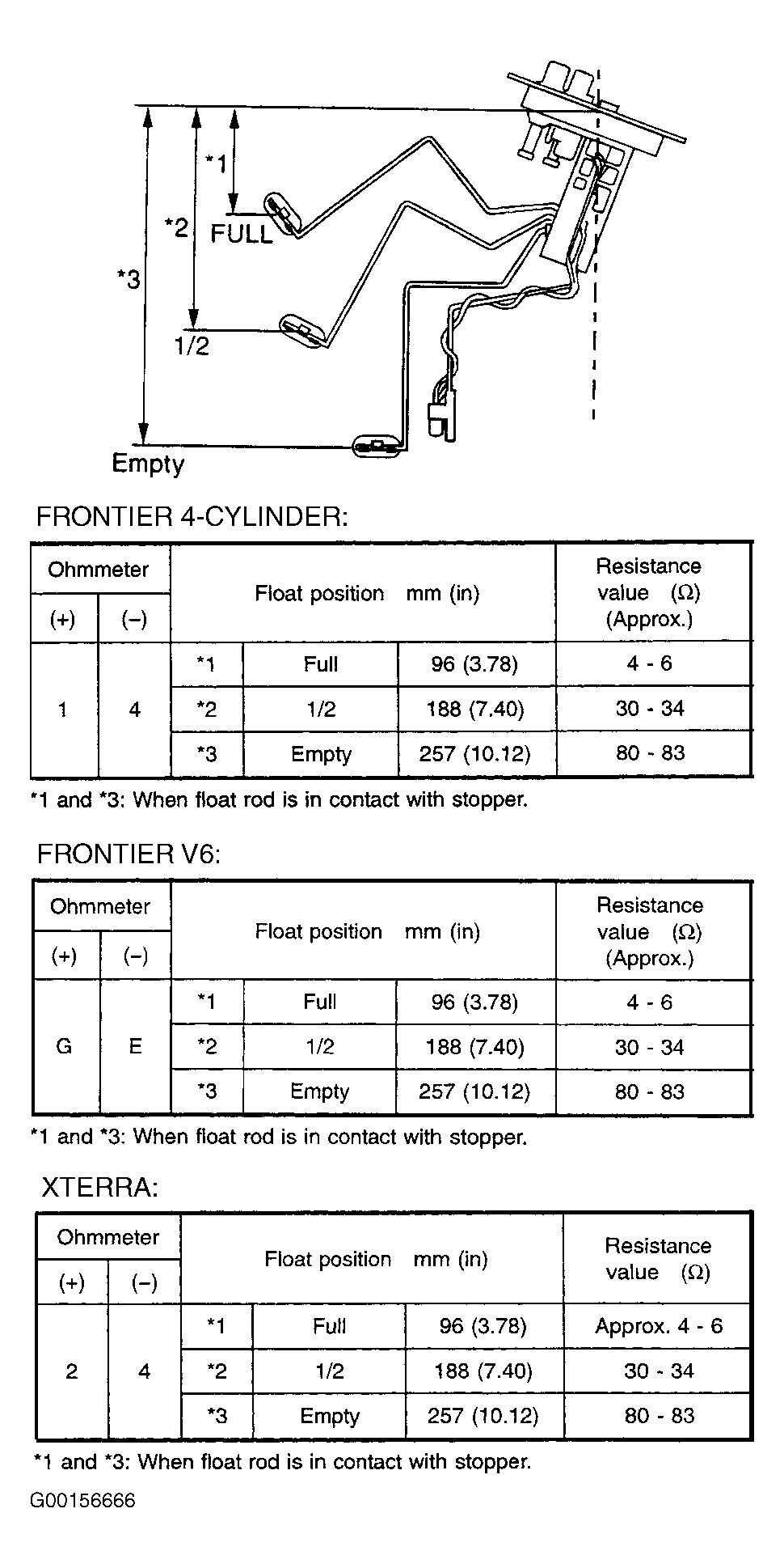 Courtesy of NISSAN MOTOR CO., U.S.A.