DTC P1220: Fuel Pump Control Module (FPCM) (2.0L Models Only): Procedure
- Turn ignition off. Disconnect Fuel Pump Control Module (FPCM) harness connector. See Fig 1. Turn ignition on. Using DVOM, measure voltage between FPCM harness connector terminal No. 3 (Black/Yellow wire) and ground. See Fig 2. If battery voltage is present, go to next step. If battery voltage is not present, repair open in short in Black/Yellow wire.
- Turn ignition off. Disconnect dropping resistor harness connector. See Fig 1. Using DVOM, check continuity between FPCM harness connector terminal No. 2 (Black wire), dropping resistor harness connector terminal No. 1 (Black wire) and ground. If continuity exists, go to next step. If continuity does not exist, repair open in Black wire.
- Disconnect fuel pump harness connector. See Fig 3. Using DVOM, check continuity between fuel pump harness connector terminal No. 2 and dropping resistor harness connector terminal No. 2 (Green/Red wire). Also check continuity between dropping resistor harness connector terminal No. 2 and FPCM harness connector terminal No. 2 (Green/Red wire). If continuity exists, go to next step. If continuity does not exist, repair open in Green/Red wire.
- Using DVOM, check continuity between ground and FPCM harness connector terminal No. 1 and fuel pump harness connector terminal No. 2 (Green/Red wire). If continuity does not exist, go to next step. If continuity does exist, repair short in Green/Red wire.
- Disconnect PCM harness connector. See Figure. Using DVOM, check continuity between PCM harness connector terminal No. 11 and FCPM harness connector terminal No. 4 (Black/Pink wire). See Figure and Fig 2
. If continuity exists, go to next step. If continuity does not exist, repair open or short in Black/Pink wire.
- Using DVOM, check continuity between PCM harness connector terminal No. 36 and FPCM harness connector terminal No. 1 (Green/Red wire). If continuity exists, go to next step. If continuity does not exist, repair open or short in Green/Red wire.
- Check continuity between PCM harness connector terminal No. 36 (Green/Red wire) and ground. If continuity does not exist, go to next step. If continuity exists, repair short in Green/Red wire.
- Using DVOM, measure resistance between dropping resistor terminals. Resistance should be approximately .8 ohm at 77°F (25°C). If resistance is as specified, go to next step. If resistance is not as specified, replace dropping resistor and retest system.
- Reconnect all connectors. Start engine and warm to operating temperature. Turn ignition off and wait 5 seconds. Connect DVOM to FPCM harness connector terminals No. 1 and No. 2 by backprobing connector terminals. While monitoring DVOM, start engine again and allow it to idle. With ignition in start position, voltage should be zero. With engine started and idling, voltage should be 5 volts. If voltage is as specified, go to next step. If voltage is not as specified, replace FPCM and retest system.
- Check all harness connector pin terminals for damage or corrosion. Repair as necessary and retest system.
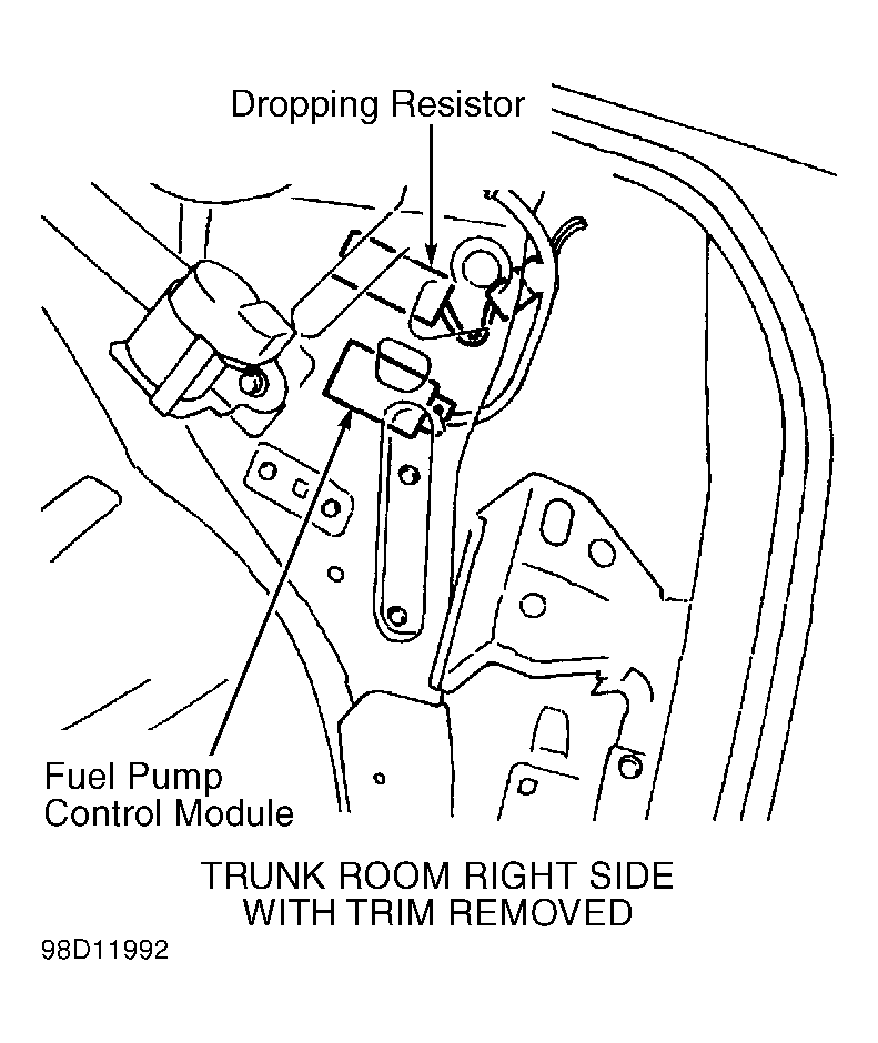 Courtesy of NISSAN MOTOR CO., U.S.A.
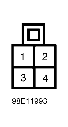 Courtesy of NISSAN MOTOR CO., U.S.A.
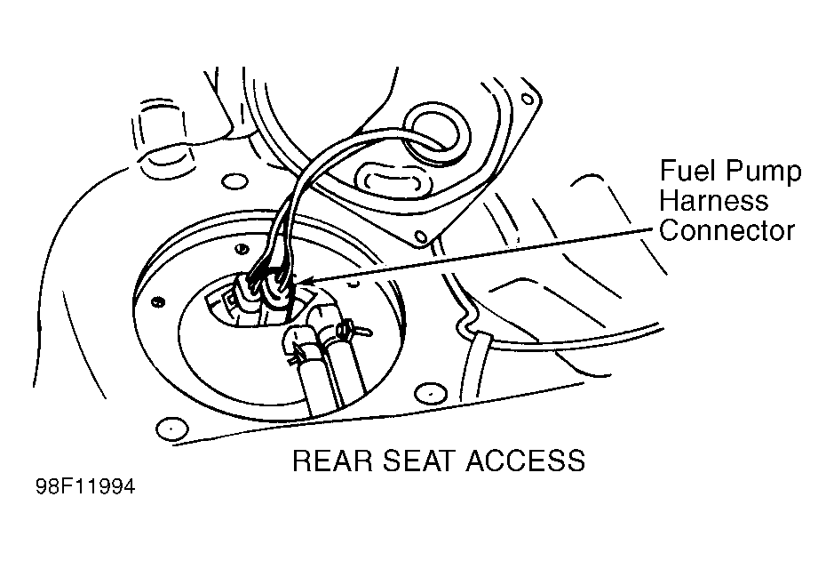 Courtesy of NISSAN MOTOR CO., U.S.A.