DTC 43: Throttle Position (TP) Sensor
- Check Power Supply
- Turn ignition off. Disconnect TP sensor harness connector. See Fig 1. Turn ignition on. Measure voltage between TP sensor connector terminal "c" (Brown wire) and ground. See Fig 2. If voltage is about 5 volts, go to next step. If voltage is not as specified, repair harness or connectors as necessary.
- Check Ground Circuit
- Turn ignition off. Check continuity between TP sensor connector terminal "a" (White/Black wire) and engine ground. See Fig 3. If continuity is present, go to next step. If continuity is not present, repair harness or connectors as necessary.
- Check Input Signal Circuit
- Disconnect ECM harness connector. See Figure. Ensure continuity exists between ECM connector terminal No. 20 and TP sensor connector terminal "b" (Red wire). See Figure and Fig 4
. If continuity is present, go to next step. If continuity is not present, repair harness or connectors as necessary.
- Check Component
- Inspect TP sensor. See I SYS/COMP TESTS article in the ENGINE PERFORMANCE section. Replace TP sensor if necessary and perform FINAL CHECK in this article. If TP sensor is okay, repair ECM pin terminals and/or wiring harness connector.
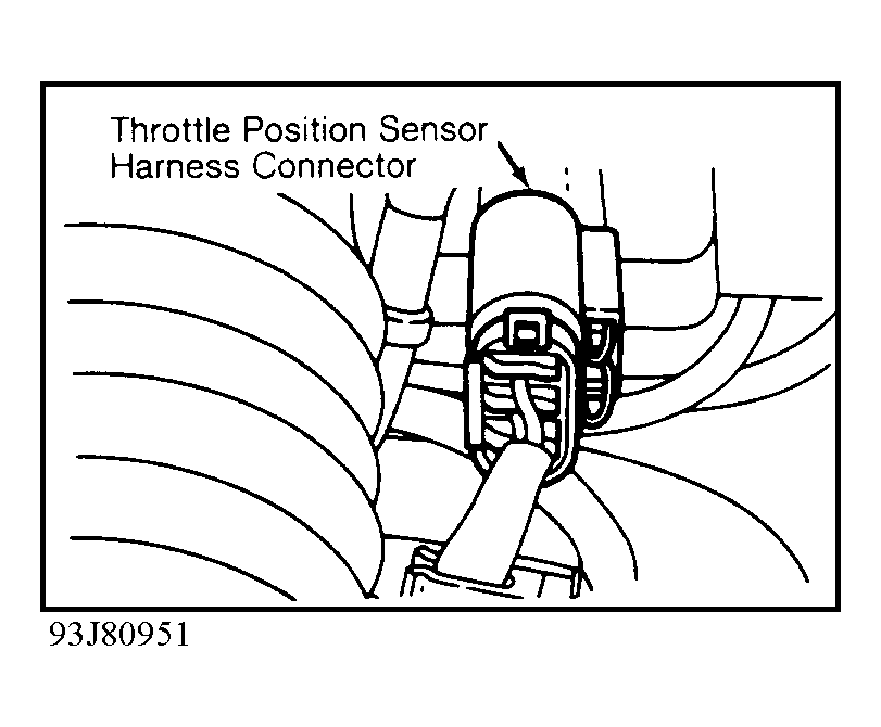 Courtesy of NISSAN MOTOR CO., U.S.A.
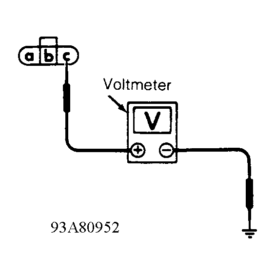 Courtesy of NISSAN MOTOR CO., U.S.A.
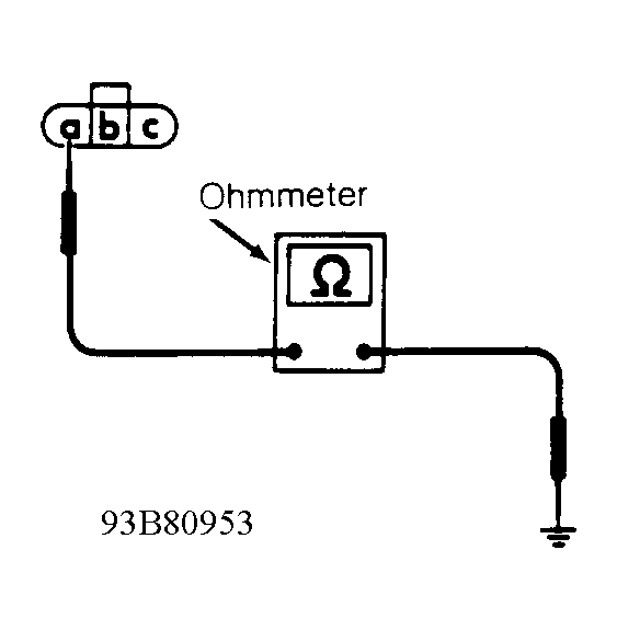 Courtesy of NISSAN MOTOR CO., U.S.A.
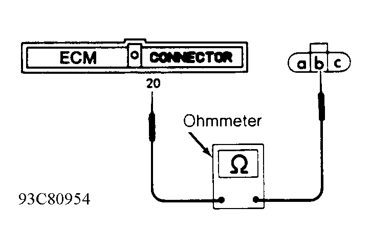 Courtesy of NISSAN MOTOR CO., U.S.A.