Pinpoint Test C: Transmission Control (TC) Switch Is Not Operating Correctly
- C1 CHECK SMART JUNCTION BOX (SJB) FUSE F20 (10A)
- Key in OFF position.
- Check fuse: SJB F20 (10A)
- Is the resistance less than 5 ohms?
- YES
: REINSTALL the fuse. Go to C3 .
- NO
: INSTALL a new fuse. TEST the system for normal operation. If the fuse fails again, go to C2 .
- C2 CHECK THE CIRCUIT FOR A SHORT TO GROUND
- Disconnect: Powertrain Control Module (PCM) C175b
- Inspect for damaged or pushed-out pins, corrosion or loose wires. Repair as necessary.
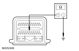 Courtesy of FORD MOTOR CO.
- Measure the resistance between PCM C175b-29 and ground.
- Is the resistance greater than 10,000 ohms?
- YES
: Go to C3.
- NO
: REPAIR circuit. TEST the system for normal operation.
- C3 CHECK THE TC SWITCH CIRCUIT FOR VOLTAGE
- Disconnect: PCM C175b
- Inspect for damaged or pushed-out pins, corrosion or loose wires. Repair as necessary.
- Leave PCM disconnected
- Key in ON position.
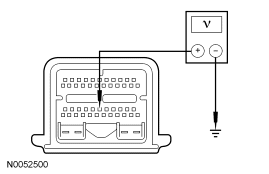 Courtesy of FORD MOTOR CO.
- Measure the voltage between PCM C175b-29 and ground while cycling the TC switch several times.
- Does the voltage cycle?
- YES
: INSTALL a new PCM. TEST the system for normal operation.
- NO
: Go to C4.
- C4 CHECK THE CIRCUIT FOR AN OPEN
- Key in OFF position.
- Disconnect: Smart Junction Box (SJB) C2280c
- Disconnect: Selector Lever C2008
- Inspect both ends for damaged or pushed-out pins, moisture, corrosion or loose wires. Repair as necessary.
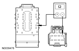 Courtesy of FORD MOTOR CO.
- Measure the resistance between SJB C2280c-12 and selector lever C2008-1, harness side.
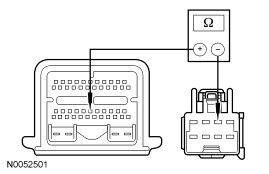 Courtesy of FORD MOTOR CO.
- Measure the resistance between PCM C175b-29 and selector lever C2008-2, harness side.
- Is the resistance less than 5 ohms for both circuits?
- YES
: Go to C5.
- NO
: REPAIR open circuit. RECONNECT all components. TEST the system for normal operation.
- C5 CHECK THE CIRCUIT FOR A SHORT TO POWER
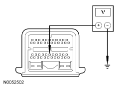 Courtesy of FORD MOTOR CO.
- Measure the voltage between PCM C175b-29 and ground.
- Is the voltage greater than 10 volts?
- YES
: INSTALL a new transmission control switch. RECONNECT all components. TEST the system for normal operation.
- NO
: REPAIR circuit. TEST the system for normal operation.