Pinpoint Test A: The Powertrain Control Module (Pcm) Does Not Respond To The Diagnostic Tool
- A1 CHECK THE HIGH SPEED CAN CIRCUITS BETWEEN THE PCM AND THE DLC FOR AN OPEN
- Key in OFF position.
- Disconnect: PCM C175b.
- Measure the resistance between the PCM C175b-11, circuit 1908 (WH), harness side and the DLC C251-6, circuit 1908 (WH), harness side; and between the PCM C175b-23, circuit 1909 (BK), harness side and the DLC C251-14, circuit 1909 (BK), harness side.
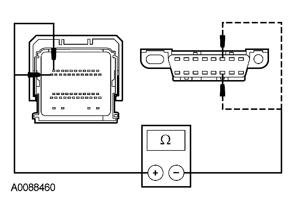 Courtesy of FORD MOTOR CO.
- Are the resistances less than 5 ohms?
- Yes
: GO to A2.
- No
: REPAIR the circuit in question. CLEAR the DTCs. REPEAT the self-test. CARRY OUT the diagnostic tool data link test.
- A2 CHECK FOR CORRECT PCM OPERATION
- Disconnect all the PCM connectors.
- Check for:
- corrosion
- pushed-out pins
- Connect all the PCM connectors and make sure they seat correctly.
- Operate the system and verify the concern is still present.
- Is the concern still present?
- Yes
: DIAGNOSE the high speed CAN. GO to PINPOINT TEST H .
- No
: The system is operating correctly at this time. The concern may have been caused by a loose or corroded connector. CLEAR the DTCs. REPEAT the self-test. CARRY OUT the diagnostic tool data link test.