Test B: Anti-Lock Brake System (Abs) Module Does Not Respond To NGS Tester
- Turn ignition switch to LOCK position. Disconnect NGS tester (if connected). Disconnect ABS module harness connector C385. Inspect connector for loose, damaged or corroded terminals. If connector is okay, go to next step. If connector is damaged, repair connector as necessary.
- Measure resistance between terminal No. 24 (White/Violet wire) at ABS module harness connector C385 and terminal No. 7 (White/Blue wire) at Data Link Connector (DLC). See Figure
and Fig 1
. If resistance is 5 ohms or less, go to next step. If resistance is greater than 5 ohms, repair open in White/Blue and/or White/Violet wire between ABS module harness connector and DLC.
- If vehicle is equipped with traction control, go to next step. If vehicle is not equipped with traction control, replace ABS module if ABS module power and ground circuits are okay.
- Measure resistance between terminal No. 29 (Blue wire) at ABS module harness connector C385 and terminal No. 10 (Blue/White wire) at DLC. If resistance is 5 ohms or less, go to next step. If resistance is greater than 5 ohms, repair open in Blue and/or Blue/White wire between ABS module harness connector and DLC.
- Measure resistance between terminal No. 30 (Gray wire) at ABS module harness connector C385 and terminal No. 2 (Gray/Violet wire) at DLC. If resistance is 5 ohms or less, replace ABS module if ABS module power and ground circuits are okay. If resistance is greater than 5 ohms, repair open in Gray or Gray/Violet wire between ABS module harness connector and DLC.
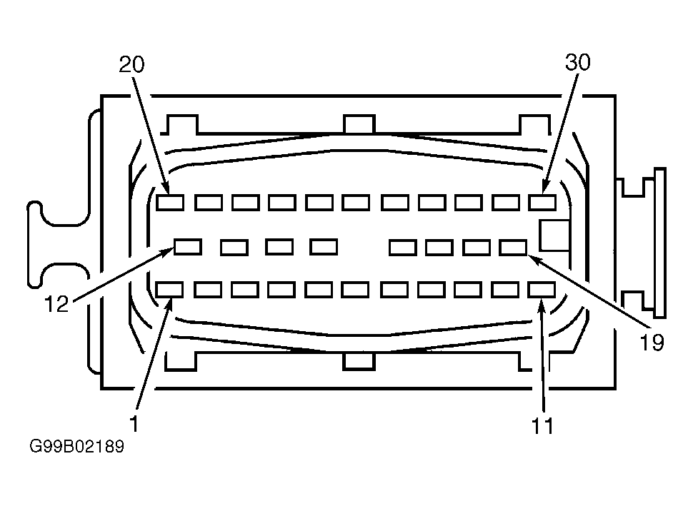 Courtesy of FORD MOTOR CO.