Abs Quick Test
- Check for insufficient brake fluid, leaks, damaged sensors, rotors or hydraulic actuator assembly. Check ABS wiring harness for proper connections, pins, corrosion, loose wiring and/or proper routing. Check all fuses. Check ABCM (ABCM) for any physical damage. If components are okay, go to next step. If components are not okay, repair or replace as needed, then go to next step.
- Perform all of the following safety steps:
- Apply parking brake.
- Place shift lever in Park.
- Block drive wheels.
- Turn off all electrical loads (radio, lights, fan, A/C, etc.).
After performing listed steps, go to next step.
- Turn ignition on. Observe ABS warning light. If light comes on for about 3 seconds then goes out, go to next step. If light does not come on at all, go to TEST A
. If light stays on, go to next step.
- Start engine. Test drive vehicle if needed to repeat problem. Observe ABS warning light. If warning light comes on, a present failure exists. Go to next step. If warning light does not come on, ABS system is operating properly, or an intermittent problem exists. Problem may also be in non-ABS portion of braking system. Go to next step.
- Turn ignition off. Place jumper wire between pin No. 4 of Data Link Connector (DLC) and ground. See Fig 1
. Turn ignition switch to ON position. Observe ABS warning light. Code 12 will flash (start code), then any additional Diagnostic Trouble Codes (DTCs) will be flashed in sequence. Record any codes. If any codes are present, go to DIAGNOSTIC TROUBLE CODE INDEX
. If no codes are retrieved, but warning light stays on, go to TEST D
. If warning light does not come on, go to TEST A
.
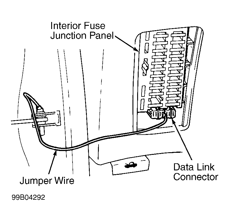 Courtesy of FORD MOTOR CO.
DIAGNOSTIC TROUBLE CODE INDEX
| Trouble Code |
Proceed To Test |
| 12 Start Code (No Faults Detected) |
B |
| 18 (ABS sensor Frequency Error) |
E |
| 21 (RF ABS Sensor) |
E |
| 22 (RF ABS Sensor) |
E |
| 25 (LF ABS Sensor) |
E |
| 26 (LF ABS Sensor) |
E |
| 31 (RR ABS Sensor) |
E |
| 32 (RR ABS Sensor) |
E |
| 35 (LR ABS Sensor) |
E |
| 36 (LR ABS Sensor) |
E |
| 41 (RF Solenoid) |
|
| 45 (LF Solenoid) |
|
| 55 (Rear Solenoid) |
|
| 61 (Hydraulic Pump Motor Circuit) |
C |
| 63 (Solenoid Relay) |
|
| 71 (ABCM) |
|
| No Code, Light On Continuously (Hydraulic Solenoid Circuit) |
D |
| No Code, Light Not On (ABCM Power Supply) |
A |
BREAKOUT BOX (BOB) PIN-TO-ECM PIN CHART
| ABS Electronic Control Module Pin No. |
Breakout Box Pin No. |
Wire Color |
| 1 |
1 |
Light Green |
| 2 |
51 |
Orange |
| 4 |
9, 43 |
Blue/Yellow |
| 5 |
4 |
Blue/Green |
| 8 |
45 |
White/Blue |
| 9 |
44 |
Orange/Blue |
| 11 |
56 |
Green |
| 14 |
24 |
Blue/Black |
| 17 |
28 |
Brown |
| 18 |
8 |
Green/Red |
| 20 |
52 |
Black |
| 21 |
16 |
Red |
| 24 |
49 |
Orange |
| 25 |
2 |
Yellow |
| 26 |
25 |
Black/Pink |
| 27 |
35 |
Green/Yellow |
| 28 |
34 |
White/Green |
| 29 |
17 |
Yellow/Red |
| 30 |
48 |
Gray/Blue |
| 32 |
6 |
Purple |
| 34 |
58 |
Black |
| 35 |
32 |
Green/White |