DTC P2103
DETECTION CONDITION AND POSSIBLE CAUSE (DTC P2103 - LF, L3)
| DTC P2103 |
Throttle actuator circuit high input |
| DETECTION CONDITION |
- The PCM monitors the throttle actuator circuit current. If the PCM detects that throttle actuator circuit current is excessive high, the PCM determines that the electronic throttle actuator circuit has a malfunction.
Diagnostic support note
- This is a continuous monitor (CCM).
- The MIL illuminates if the PCM detects the above malfunction conditions during the first drive cycle.
- PENDING CODE is available if the PCM detects the above malfunction condition.
- FREEZE FRAME DATA is available.
- The DTC is stored in the PCM memory.
|
| POSSIBLE CAUSE |
- Short to power circuit between throttle body terminal E and PCM terminal 2B
- Throttle valve motor malfunction
- PCM malfunction
|
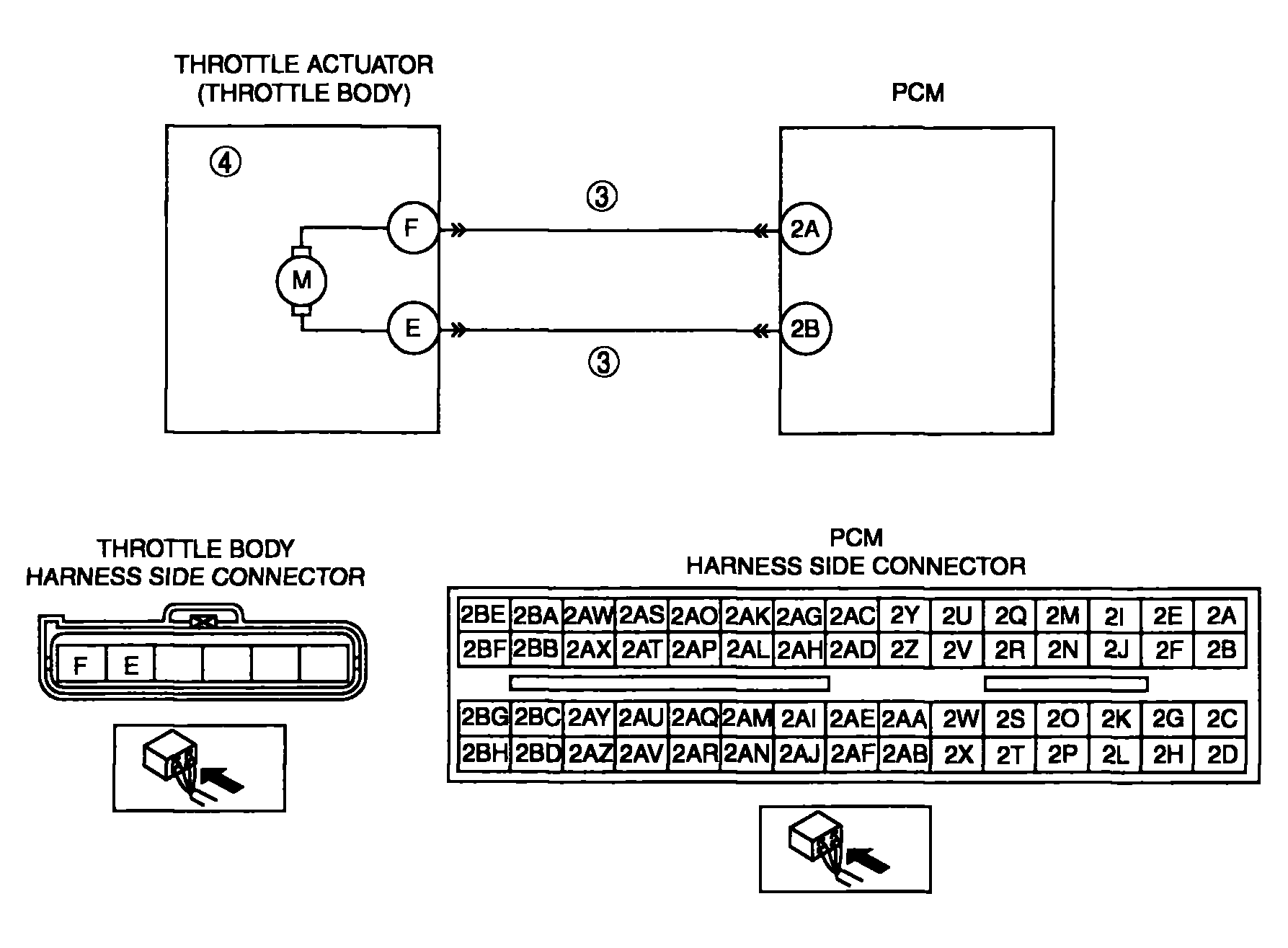 Courtesy of MAZDA MOTORS CORP. Courtesy of MAZDA MOTORS CORP.
|
DIAGNOSTIC PROCEDURE CHART
| STEP |
INSPECTION |
ACTION |
| 1 |
VERIFY FREEZE FRAME DATA HAS BEEN RECORDED
- Has FREEZE FRAME DATA been recorded?
|
Yes |
Go to the next step. |
| No |
Record the FREEZE FRAME DATA on the repair order, then go to the next step. |
| 2 |
VERIFY RELATED REPAIR INFORMATION AVAILABILITY
- Check for related Service Bulletins and/or online repair information availability.
- Is any related repair information available?
|
Yes |
Perform repair or diagnosis according to the available repair information.
- If the vehicle is not repaired, go to the next step.
|
| No |
Go to the next step. |
| 3 |
INSPECT CONTROL CIRCUIT OF THROTTLE ACTUATOR FOR SHORT TO POWER SUPPLY
- Turn the ignition switch off.
- Disconnect the throttle body and PCM connectors.
- Turn the ignition switch to the ON position (Engine off).
- Measure the voltage between the following terminals and body ground:
- Throttle body terminal E (wiring harness-side)
- Throttle body terminal F (wiring harness-side)
- Is the voltage B+
?
|
Yes |
Repair or replace the wiring harness for short circuit to power supply, then go to Step 5. |
| No |
Go to the next step. |
| 4 |
INSPECT THROTTLE ACTUATOR
|
Yes |
Go to the next step. |
| No |
Replace the throttle body, then go to the next step. |
| 5 |
VERIFY TROUBLESHOOTING OF DTC P2103 COMPLETED
- Make sure to reconnect all disconnected connectors.
- Turn the ignition switch to the ON position (Engine off).
- Clear the DTC from the PCM memory using the WDS or equivalent.
- Start the engine and warm it up completely.
- Is the same DTC present?
|
Yes |
Replace the PCM, then go to the next step. |
| No |
Go to the next step. |
| 6 |
VERIFY AFTER REPAIR PROCEDURE
|
Yes |
Go to the applicable DTC inspection. (See
DTC TABLE
). |
| No |
Troubleshooting completed. |