Disassembly Note
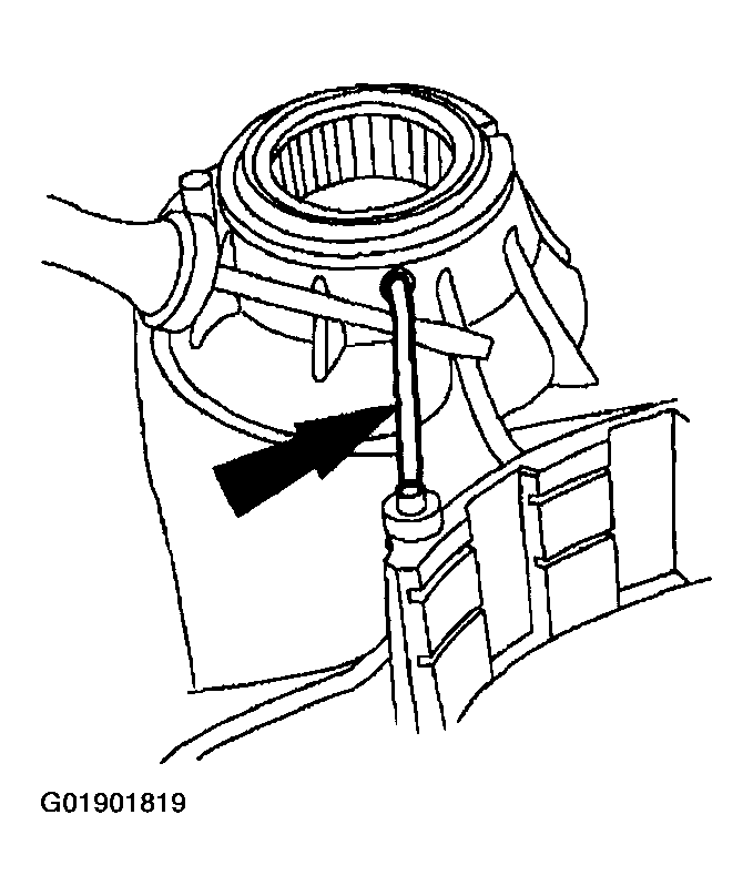 Courtesy of MAZDA MOTORS CORP.
- Remove and discard the final drive lube tube.
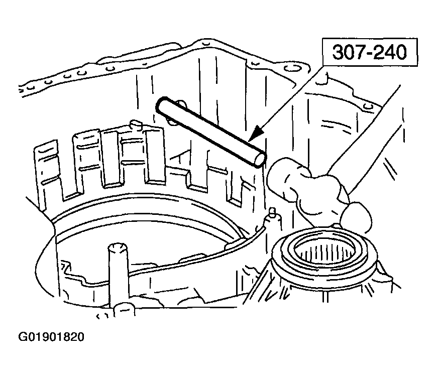 Courtesy of MAZDA MOTORS CORP.
- Using the special tool, remove and discard the final drive lube tube seal.
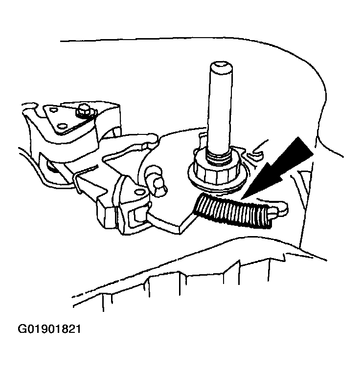 Courtesy of MAZDA MOTORS CORP.
- Remove the parking pawl ratcheting spring.
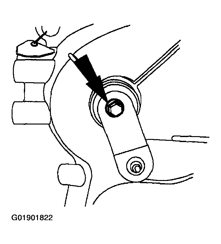 Courtesy of MAZDA MOTORS CORP.
- Remove the manual control lever outer assembly.
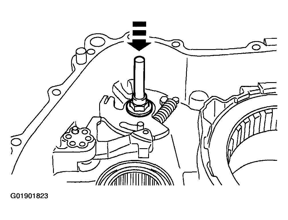 Courtesy of MAZDA MOTORS CORP.
- Remove the manual control lever shaft assembly.
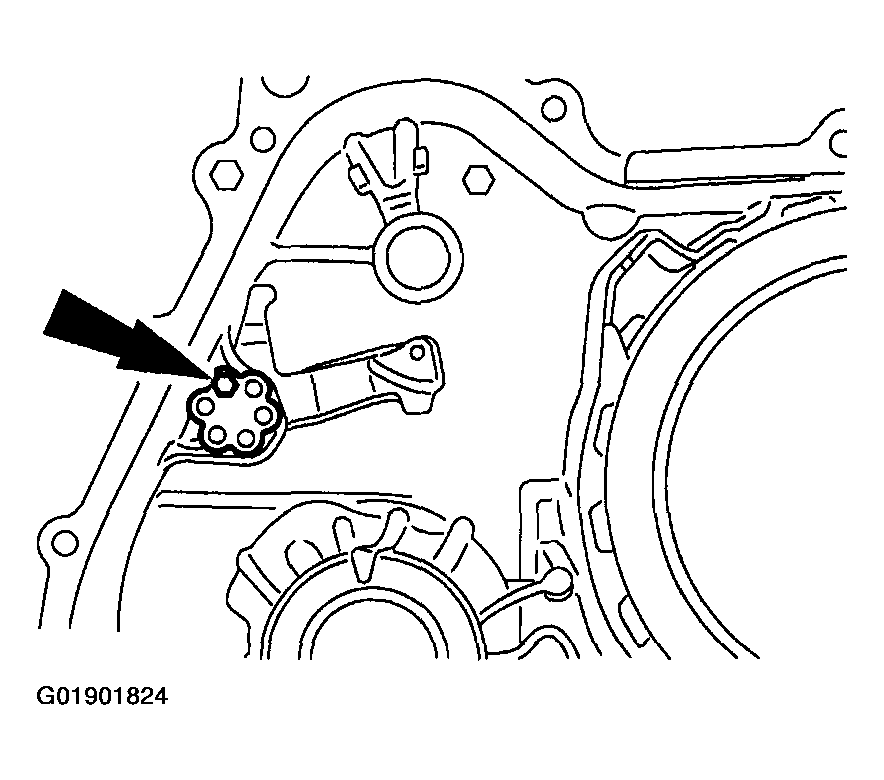 Courtesy of MAZDA MOTORS CORP.
- Remove the parking pawl shaft retainer and bolt.
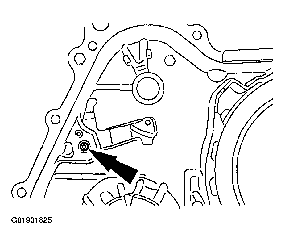 Courtesy of MAZDA MOTORS CORP.
- Remove the parking pawl shaft.
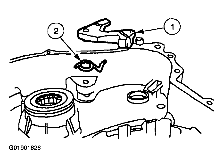 Courtesy of MAZDA MOTORS CORP.
- Remove the parking pawl assembly.
- Remove the parking pawl.
- Remove the parking pawl return spring.
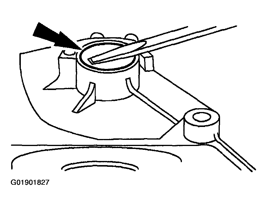 Courtesy of MAZDA MOTORS CORP.
CAUTION:
- Do not damage the transaxle case bore during seal removal.
- Remove and discard the manual control lever seal.
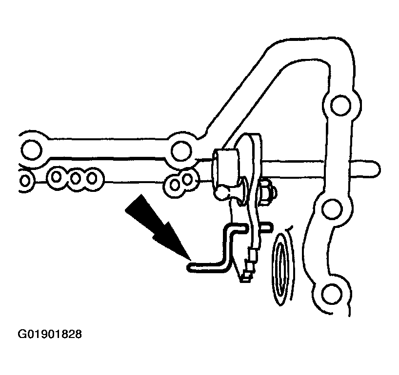 Courtesy of MAZDA MOTORS CORP.
- Remove the manual valve actuator rod (manual valve link).
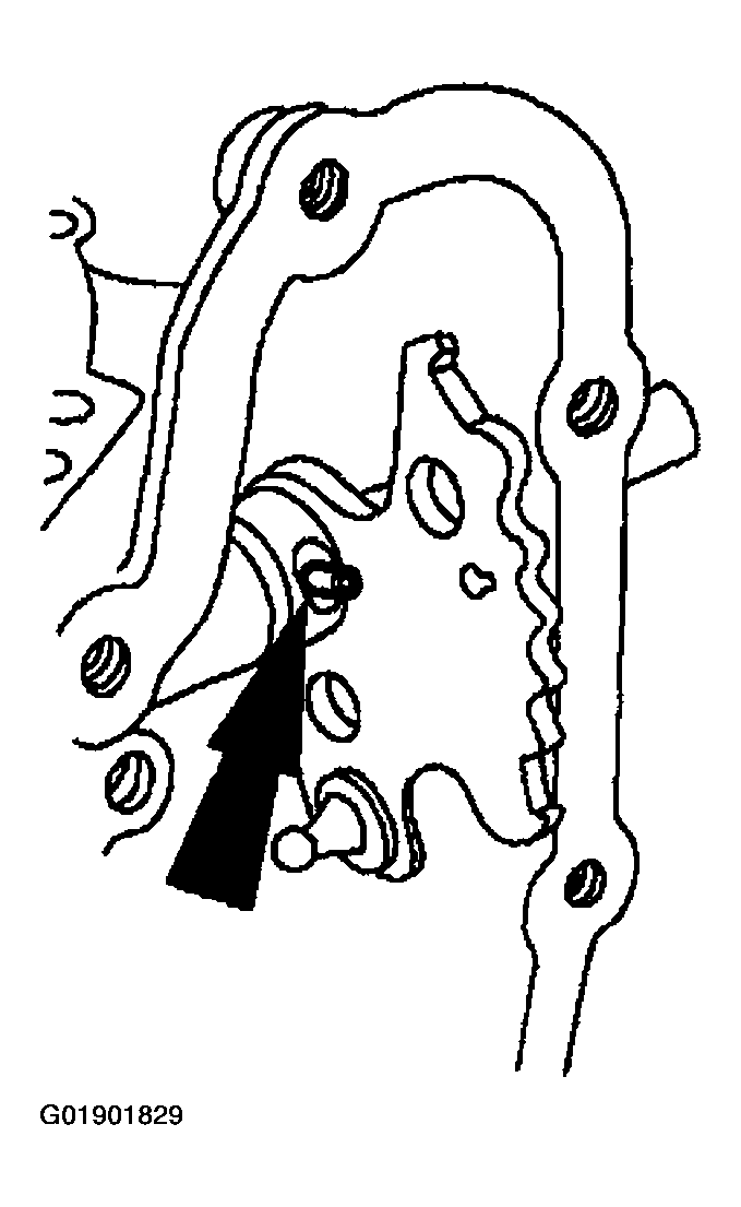 Courtesy of MAZDA MOTORS CORP.
CAUTION:
- Do not damage the transaxle case sealing surface.
- Remove and discard the manual valve detent lever shaft retaining pin.
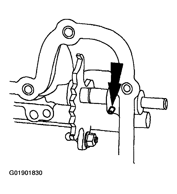 Courtesy of MAZDA MOTORS CORP.
CAUTION:
- Do not damage the transaxle case sealing surface.
NOTE:
- There are two retaining pins, one on either side of the manual valve detent lever.
- Remove the manual valve detent lever shaft retaining pin.
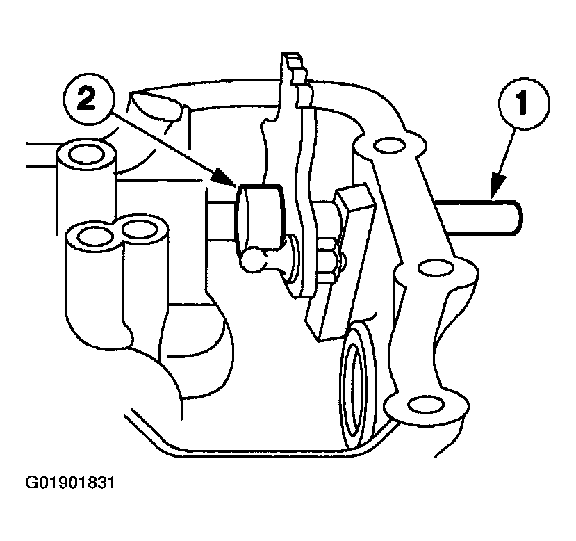 Courtesy of MAZDA MOTORS CORP.
- Remove the manual valve detent lever and shaft assembly.
- Pull the manual valve detent lever and manual valve detent lever shaft from the transaxle case.
- Lift the manual valve detent lever from the transaxle case.
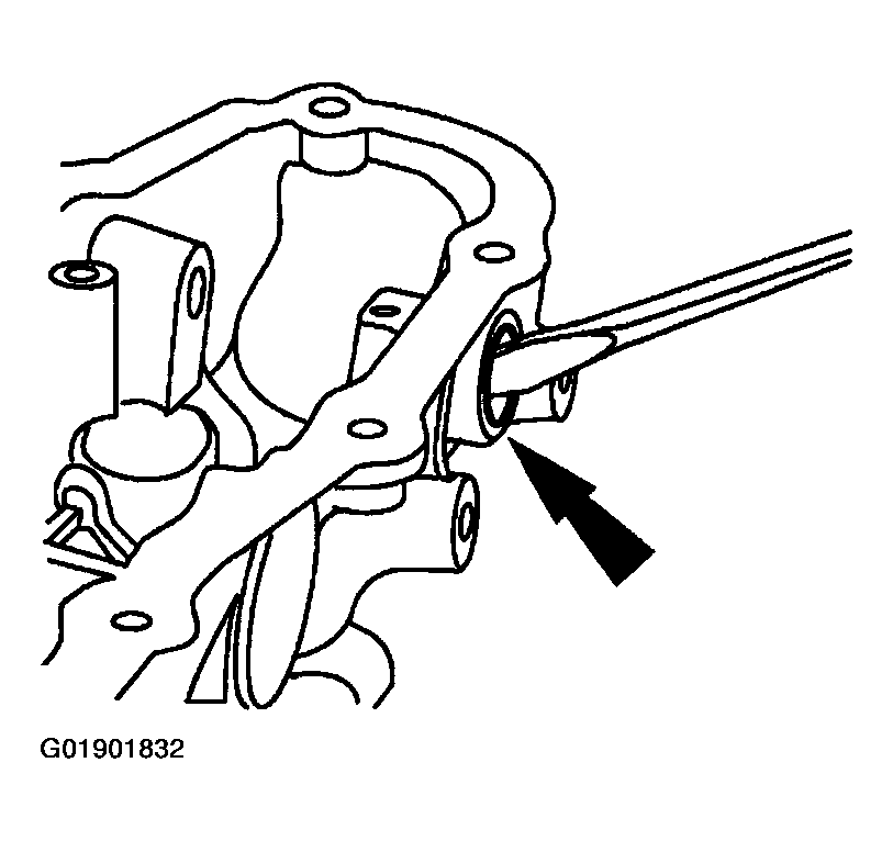 Courtesy of MAZDA MOTORS CORP.
CAUTION:
- Do not damage the seal bore in the case during seal removal.
- Remove and discard the manual control seal.
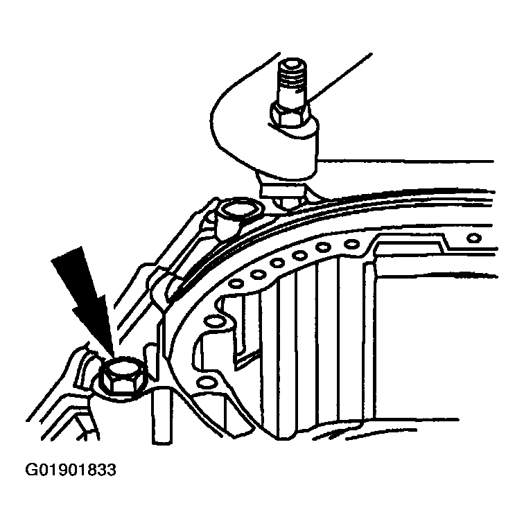 Courtesy of MAZDA MOTORS CORP.
- If the case is being replaced, remove the line pressure port plug.
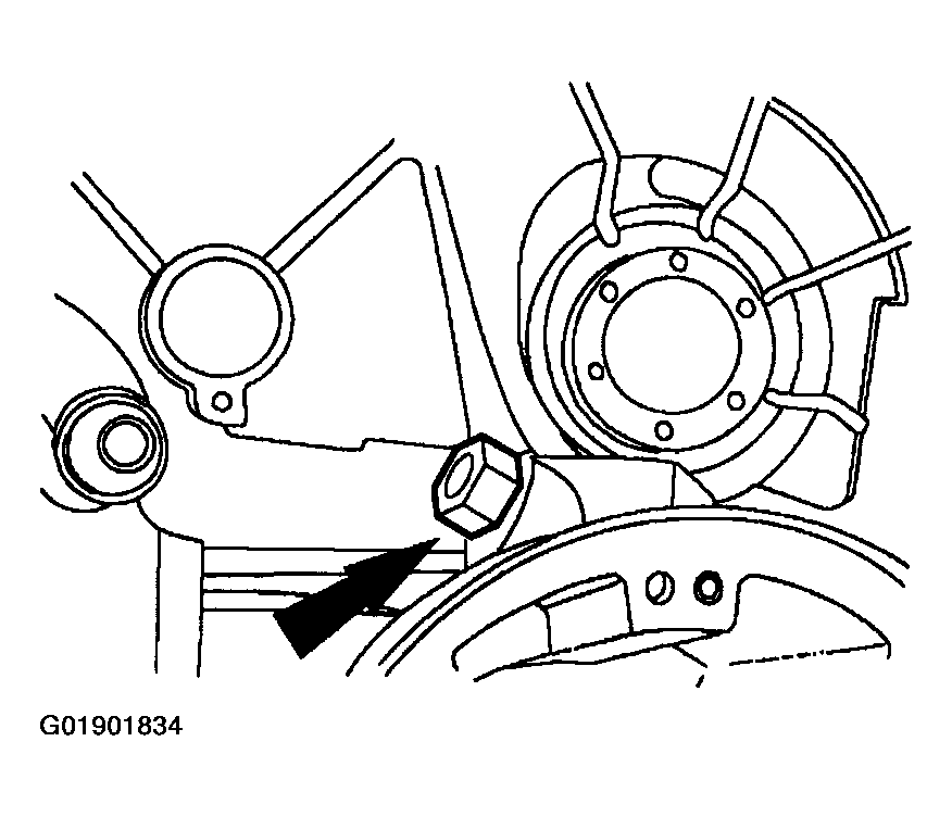 Courtesy of MAZDA MOTORS CORP.
- If a new case is being installed, remove and discard the cooler tube fitting.
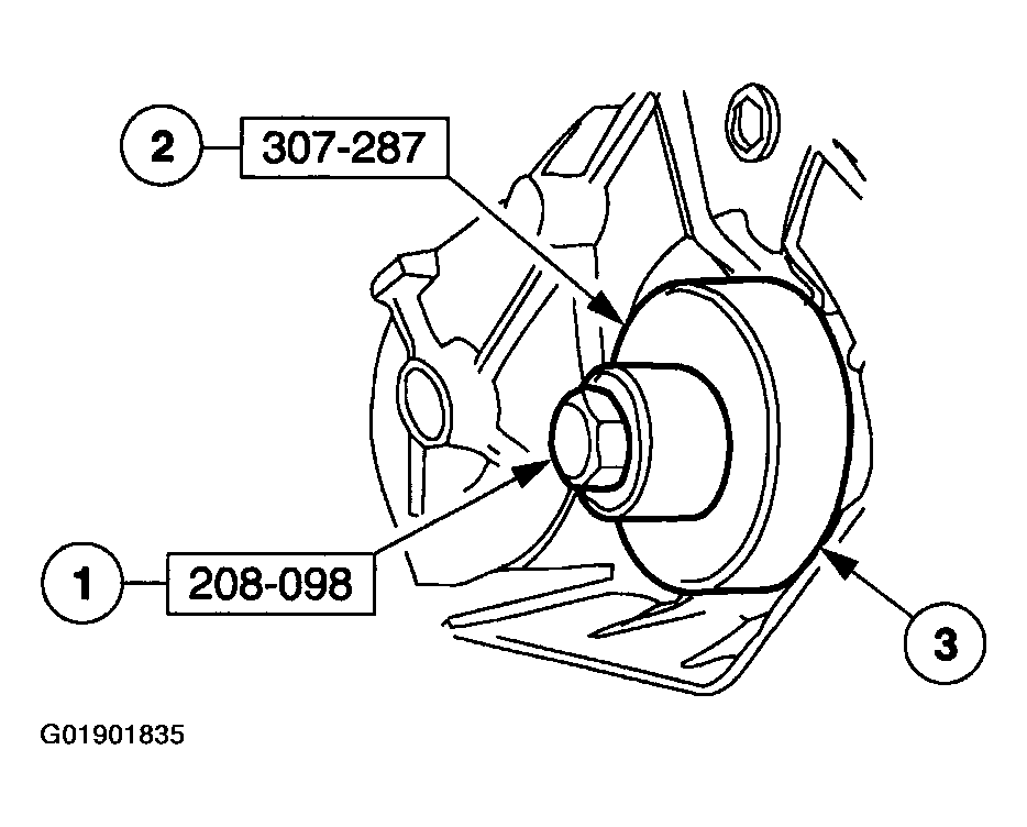 Courtesy of MAZDA MOTORS CORP.
NOTE:
- A new driven sprocket bearing No. 18 can be installed once before an installation of the transaxle case becomes necessary. If a new No. 18 driven sprocket bearing was installed previously and a second installation is required, a new transaxle case must be installed.
- As necessary, remove the No. 18 driven sprocket bearing assembly from transaxle case.
- Install the special tool into the transaxle.
- Position the special tool.
- Remove the bearing.
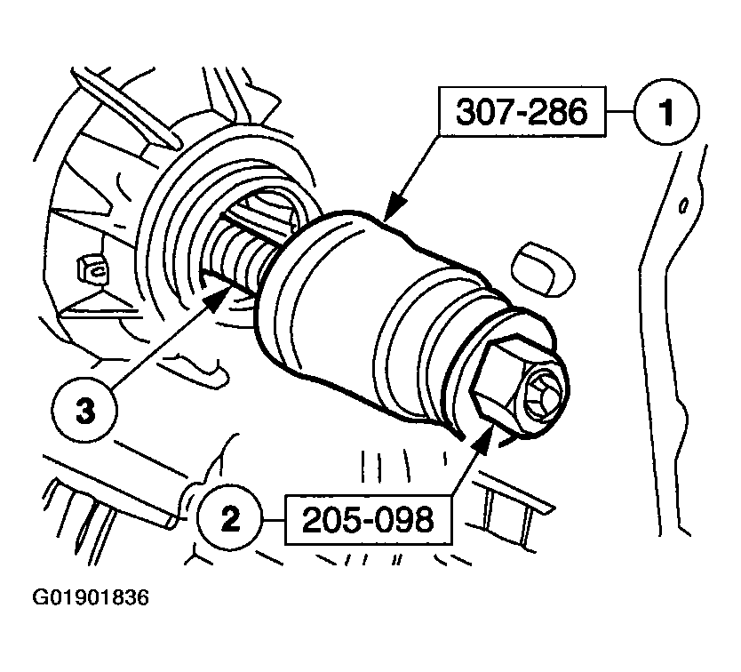 Courtesy of MAZDA MOTORS CORP.
- Using the special tools, remove the No. 18 driven sprocket bearing assembly.
- Position the special tool.
- Position the special tool.
- Remove the No. 18 driven sprocket bearing.
WARNING:
- In order to avoid injury, eye protection should be worn when cleaning components with compressed air. Failure to follow these instructions can result in personal injury.
- Clean all components with a suitable solvent and use moisture-free compressed air to dry all parts and clean fluid passages. Check the following before assembling:
- final drive lubrication tube for damage
- manual control linkage for damage or wear case mating surfaces for nicks or deformation
- bearing wear
- support area wear