Main Control Valve Body: Installation
 Courtesy of MAZDA MOTORS CORP.
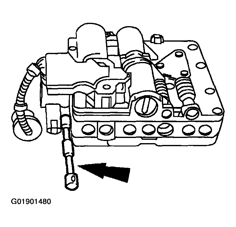
- Install the manual control valve.
 Courtesy of MAZDA MOTORS CORP.
NOTE:
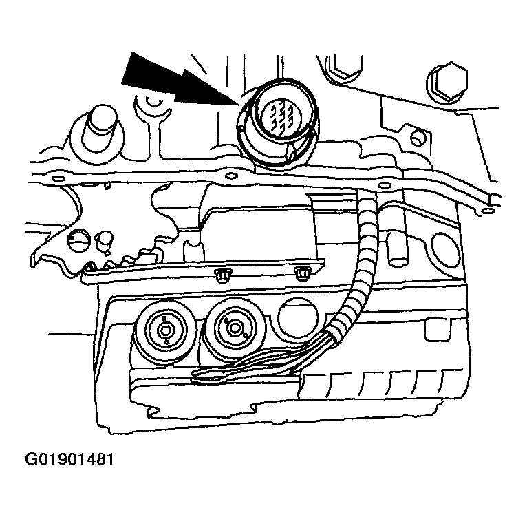
- Inspect the solenoid valve body harness connector O-ring seal for damage. Install a new O-ring seal, if damaged, before installing the connector into the case.
- Push the solenoid valve body harness connector into the case.
 Courtesy of MAZDA MOTORS CORP.
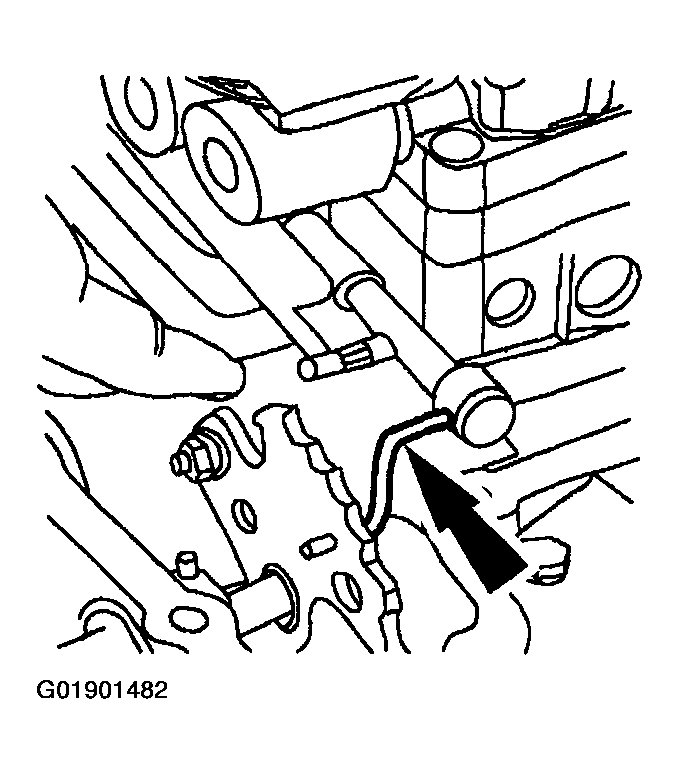
- Connect the manual valve link to the main control valve body.
 Courtesy of MAZDA MOTORS CORP.
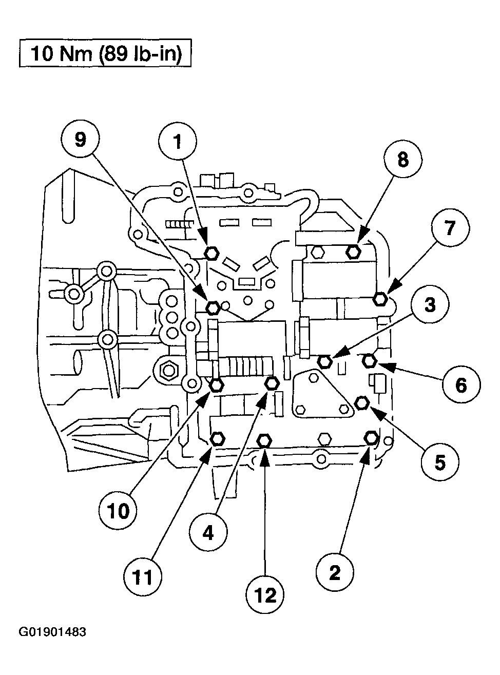
- Install the main control valve body and tighten the bolts in sequence as indicated.
 Courtesy of MAZDA MOTORS CORP.
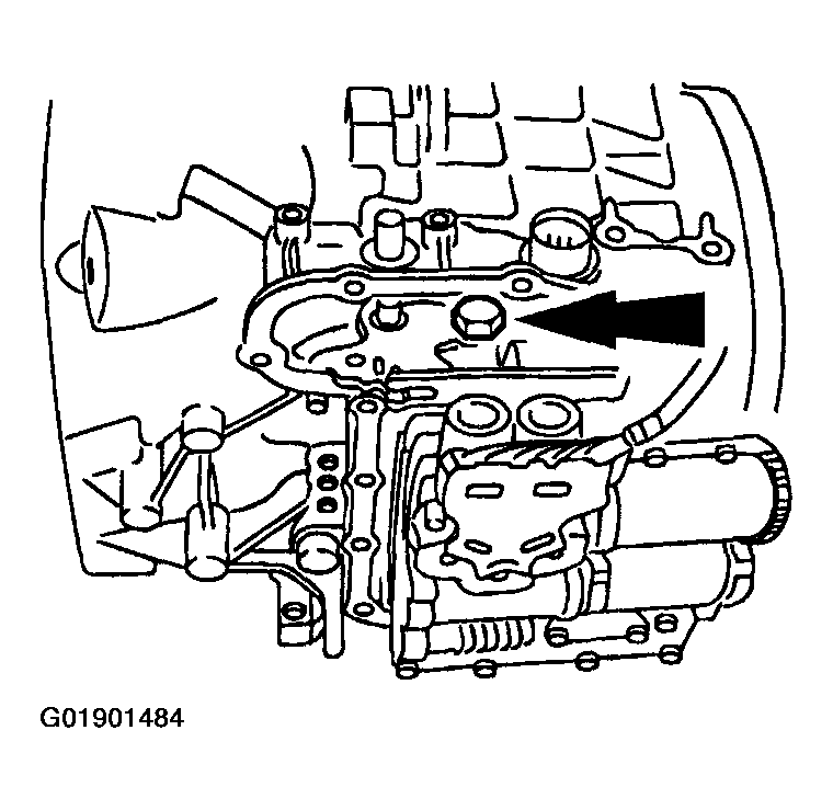
- Loosen the nut on the ball stud for the manual valve detent lever actuating rod assembly.
 Courtesy of MAZDA MOTORS CORP.
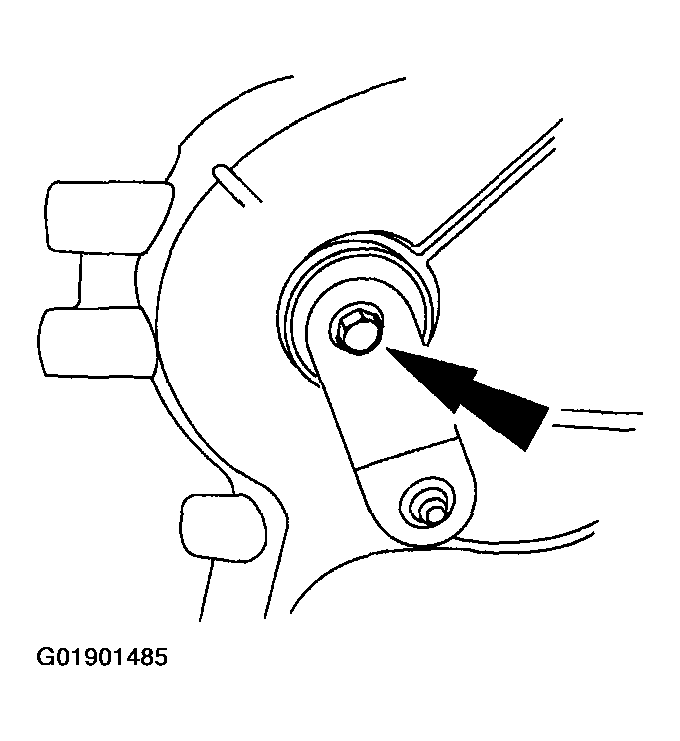
- Remove the manual control lever outer assembly bolt.
 Courtesy of MAZDA MOTORS CORP.
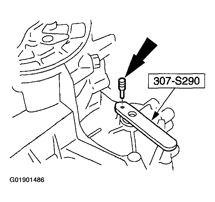
- Using the special tool and pin, align the shifter shaft.
 Courtesy of MAZDA MOTORS CORP.
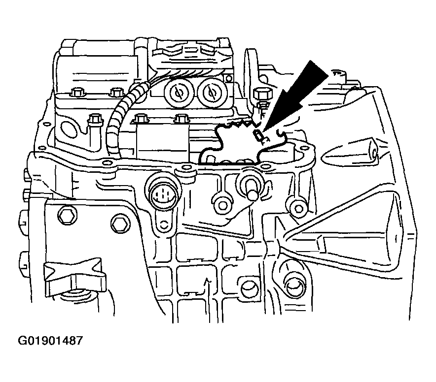
- Move the manual valve detent lever assembly to the "D" position.
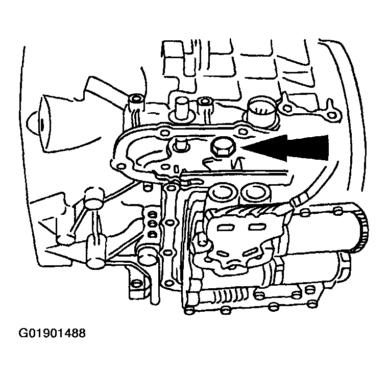 Courtesy of MAZDA MOTORS CORP.
- Tighten the nut on the ball and remove the special tool.
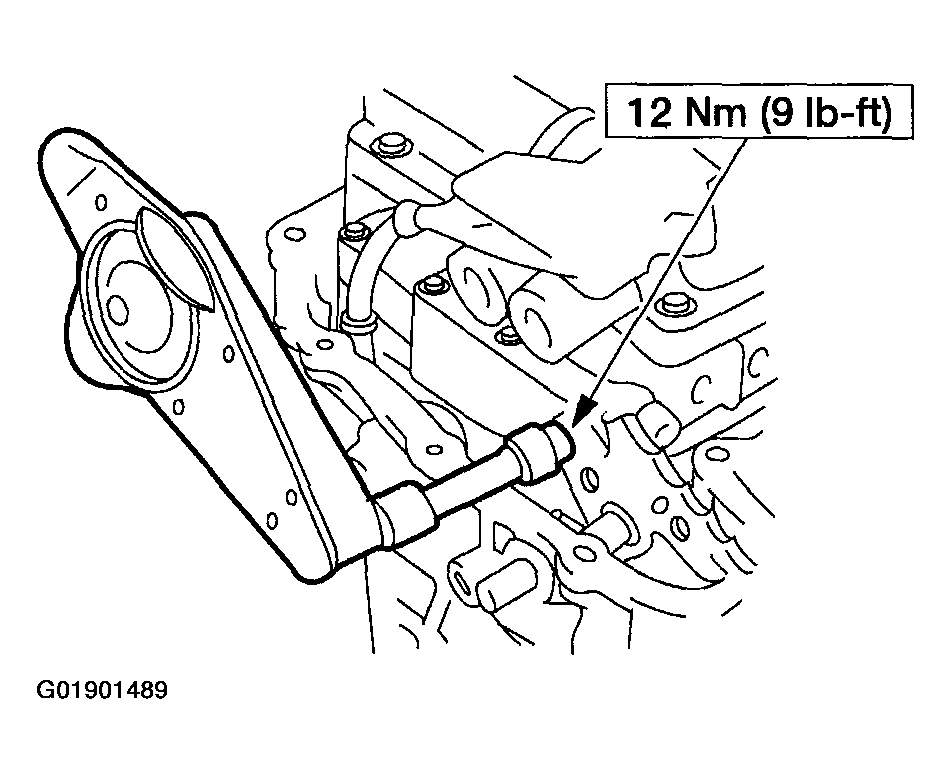 Courtesy of MAZDA MOTORS CORP.
- Tighten the detent nut. Rotate back to the "D" position and check the adjustment.
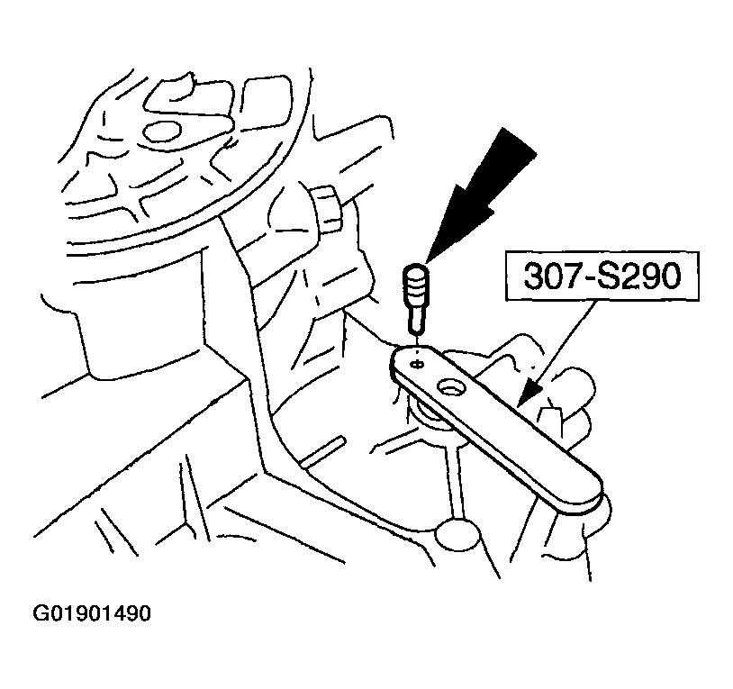 Courtesy of MAZDA MOTORS CORP.
- Using the special tool and pin, align the shifter shaft.
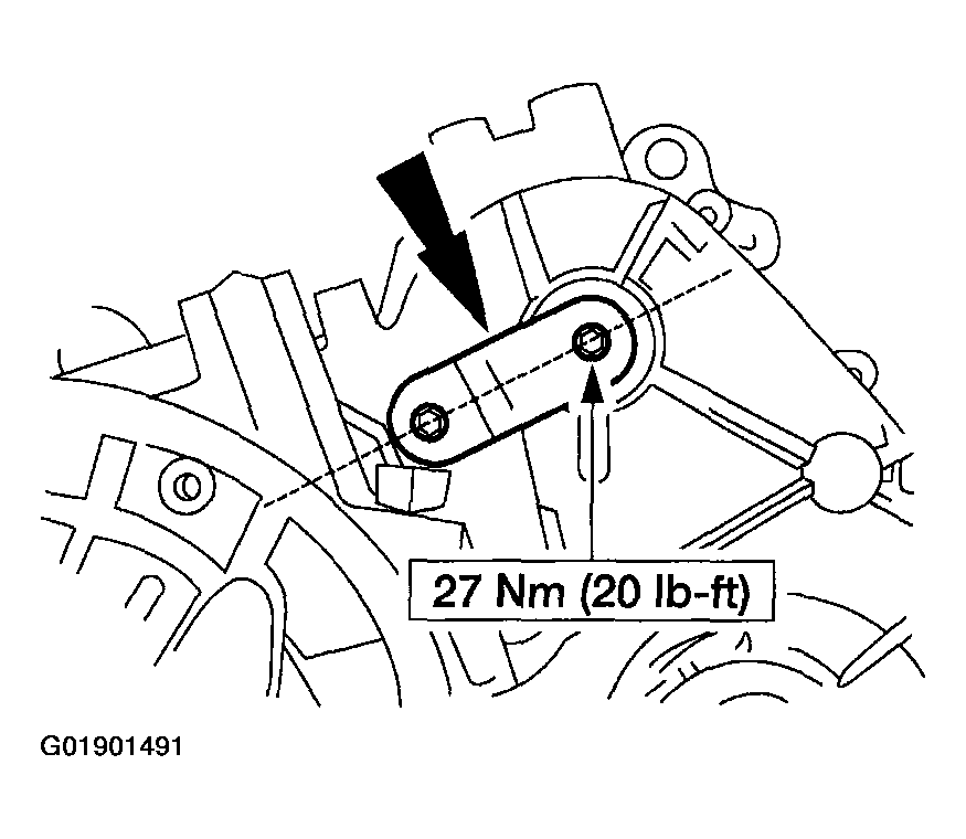 Courtesy of MAZDA MOTORS CORP.
- Install the manual control lever.
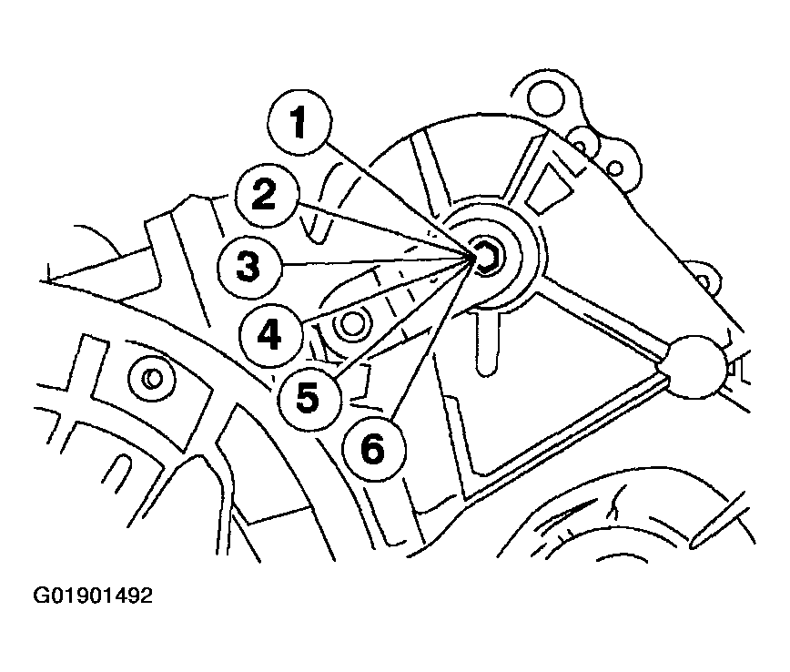 Courtesy of MAZDA MOTORS CORP.
- Install and rotate the manual valve detent lever assembly to the neutral position.
- Low 1
- Low 2
- Drive
- Neutral
- Reverse
- Park
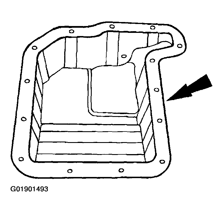 Courtesy of MAZDA MOTORS CORP.
- Install a new gasket on the main control cover.
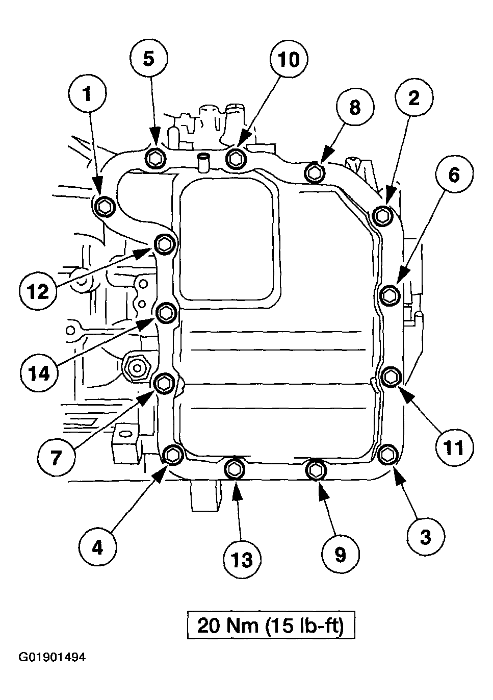 Courtesy of MAZDA MOTORS CORP.
- Install the main control cover, and tighten the bolts in sequence as shown.
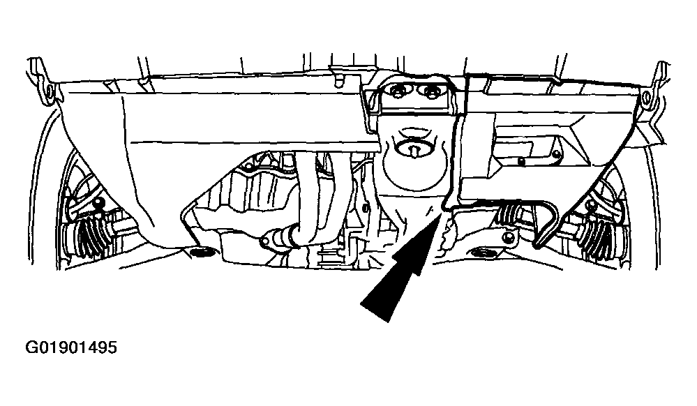 Courtesy of MAZDA MOTORS CORP.
- Install the splash shield.
- Install the LH front wheel.
- Lower the vehicle.
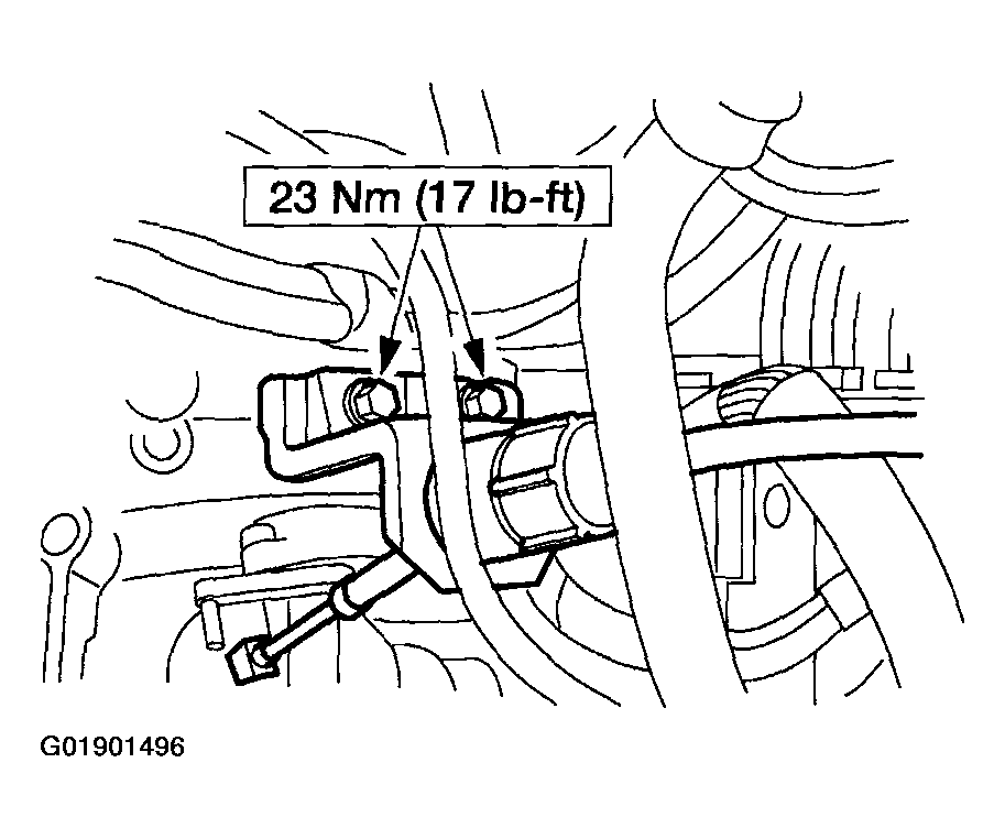 Courtesy of MAZDA MOTORS CORP.
- Install the shift cable and bracket.
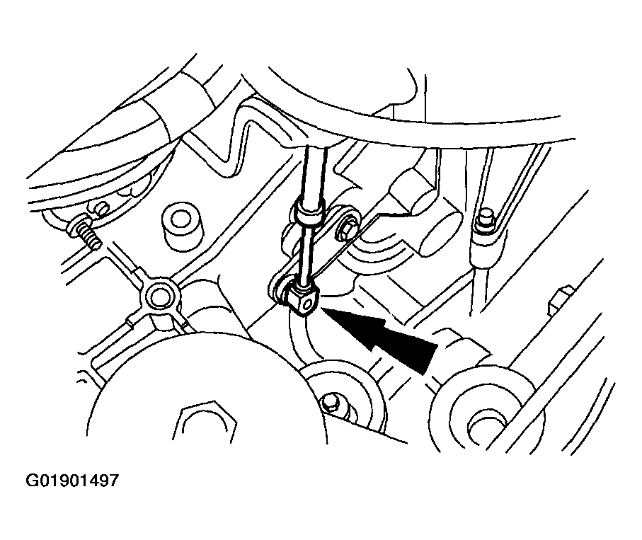 Courtesy of MAZDA MOTORS CORP.
- Connect the shift cable.
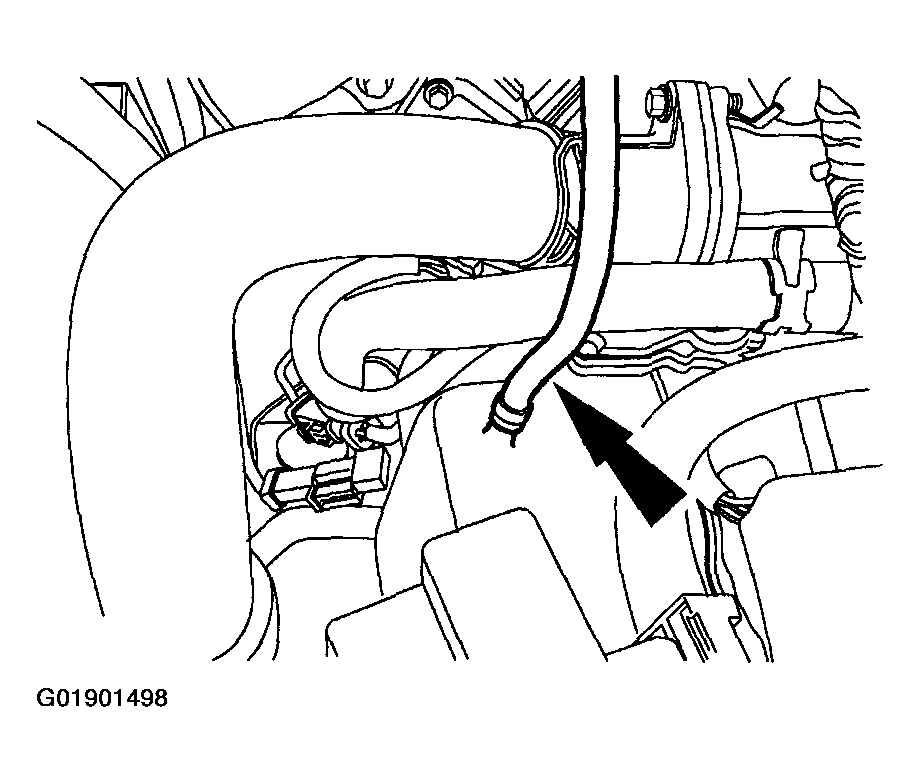 Courtesy of MAZDA MOTORS CORP.
NOTE:
- Before installing the vent tube hose, clean out any obstructions in the hose using low air pressure.
- Install the vent tube hose, and clamp.
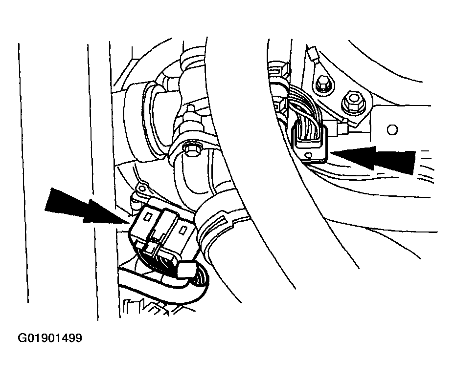 Courtesy of MAZDA MOTORS CORP.
- Connect the transaxle harness connector, and the TR sensor connector.
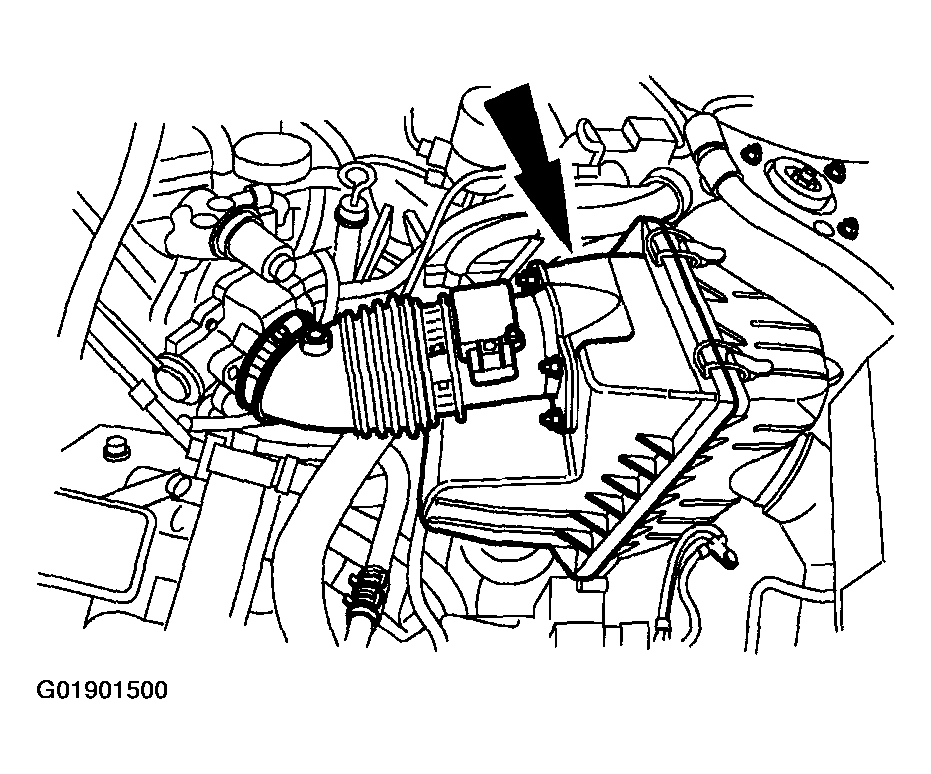 Courtesy of MAZDA MOTORS CORP.
- Install the intake tube and air cleaner cover.
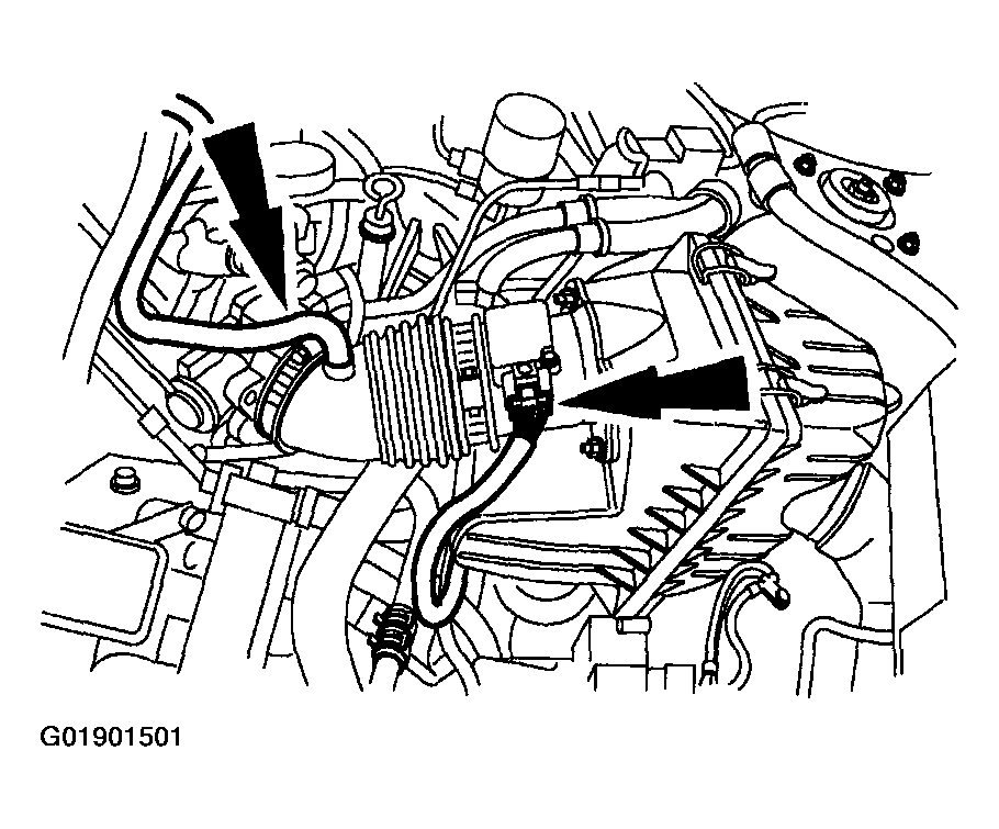 Courtesy of MAZDA MOTORS CORP.
- Connect the breather tube and mass air flow (MAF)/intake air temperature (IAT) sensor.
NOTE:
- Before installing the battery tray check the vent tube hose for any obstructions, kinks, or incorrect routing position.
- Install the battery tray and battery.
.
- Connect the battery cables.
- Check the transaxle fluid, add fluid as necessary using MERCON(R) Automatic Transaxle Fluid (ATF).
- Start the engine and move the transaxle range selector lever through all gear positions. Refill as necessary.