Assembly Note
- Soak the internal spline clutch plates in clean MERCON(R) Automatic Transaxle Fluid (ATF) for 30 minutes before assembly.
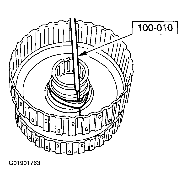 Courtesy of MAZDA MOTORS CORP.
- Install the forward clutch piston inner seal on the forward/coast/direct clutch cylinder assembly.
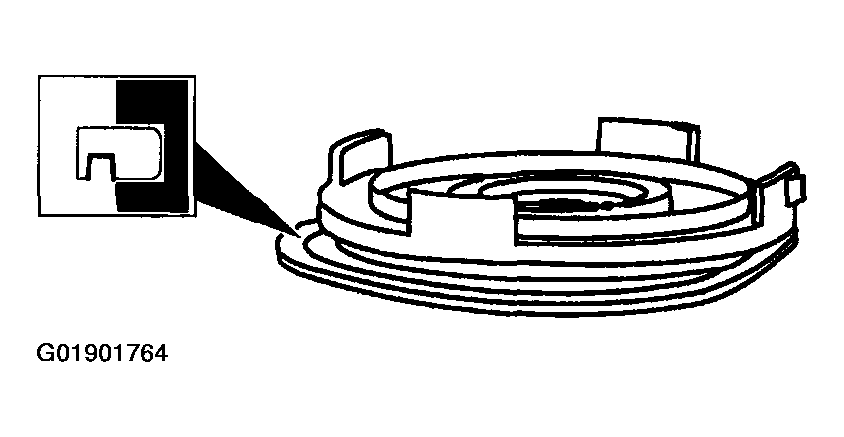 Courtesy of MAZDA MOTORS CORP.
- Install the forward clutch piston outer lip seal on the forward clutch piston assembly.
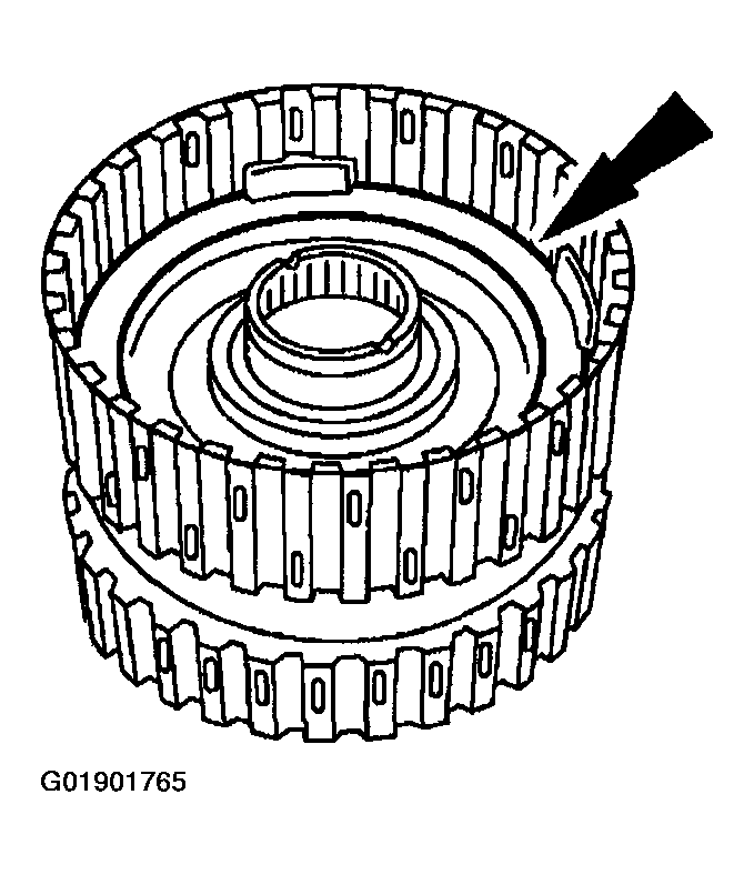 Courtesy of MAZDA MOTORS CORP.
- Install the forward clutch piston assembly in the forward/coast/direct clutch cylinder assembly.
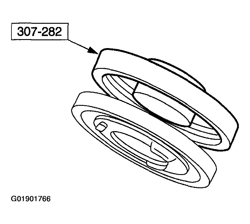 Courtesy of MAZDA MOTORS CORP.
- Install the coast clutch piston assembly onto the special tool.
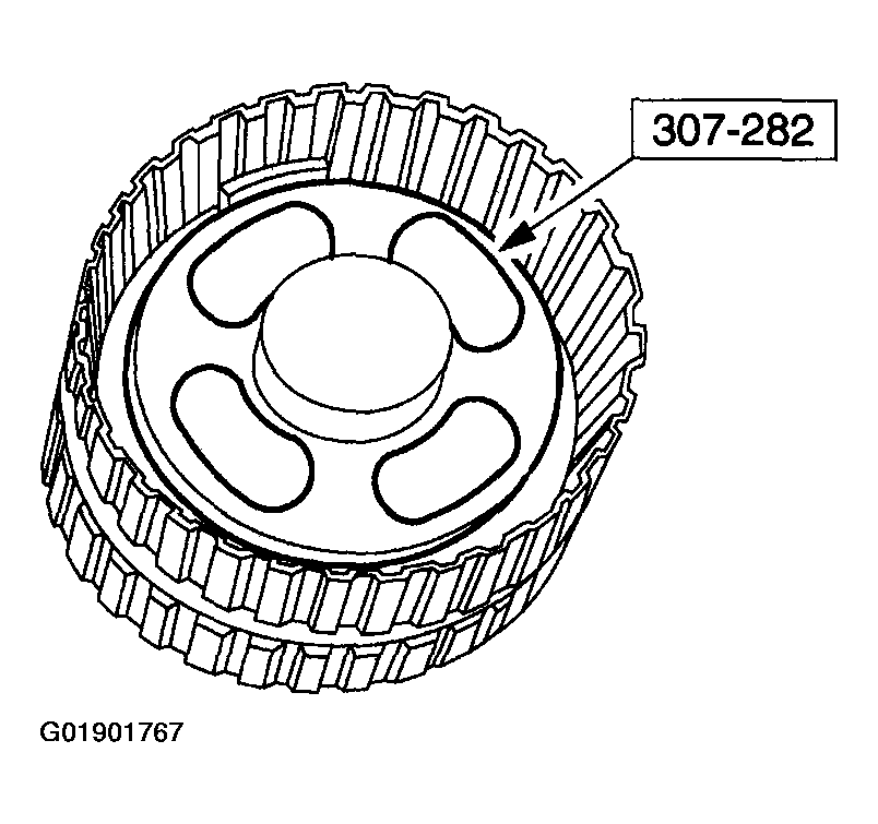 Courtesy of MAZDA MOTORS CORP.
- Using the special tool, install the coast clutch piston into the forward clutch piston assembly.
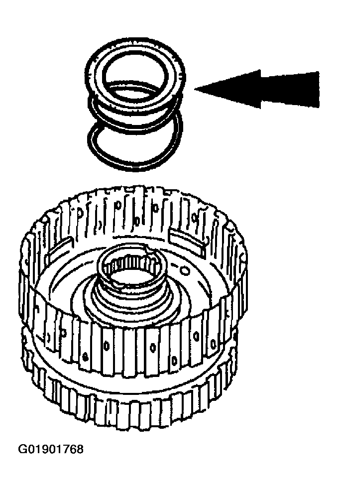 Courtesy of MAZDA MOTORS CORP.
- Install the forward/coast clutch return spring assembly.
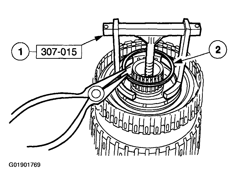 Courtesy of MAZDA MOTORS CORP.
WARNING:
- Use caution when releasing tool pressure on the clutch piston springs. Failure to follow these instructions can result in personal injury.
- Install the forward/coast clutch return spring retaining ring.
- Using the special tool, compress the return spring.
- Install the forward/coast clutch retaining ring.
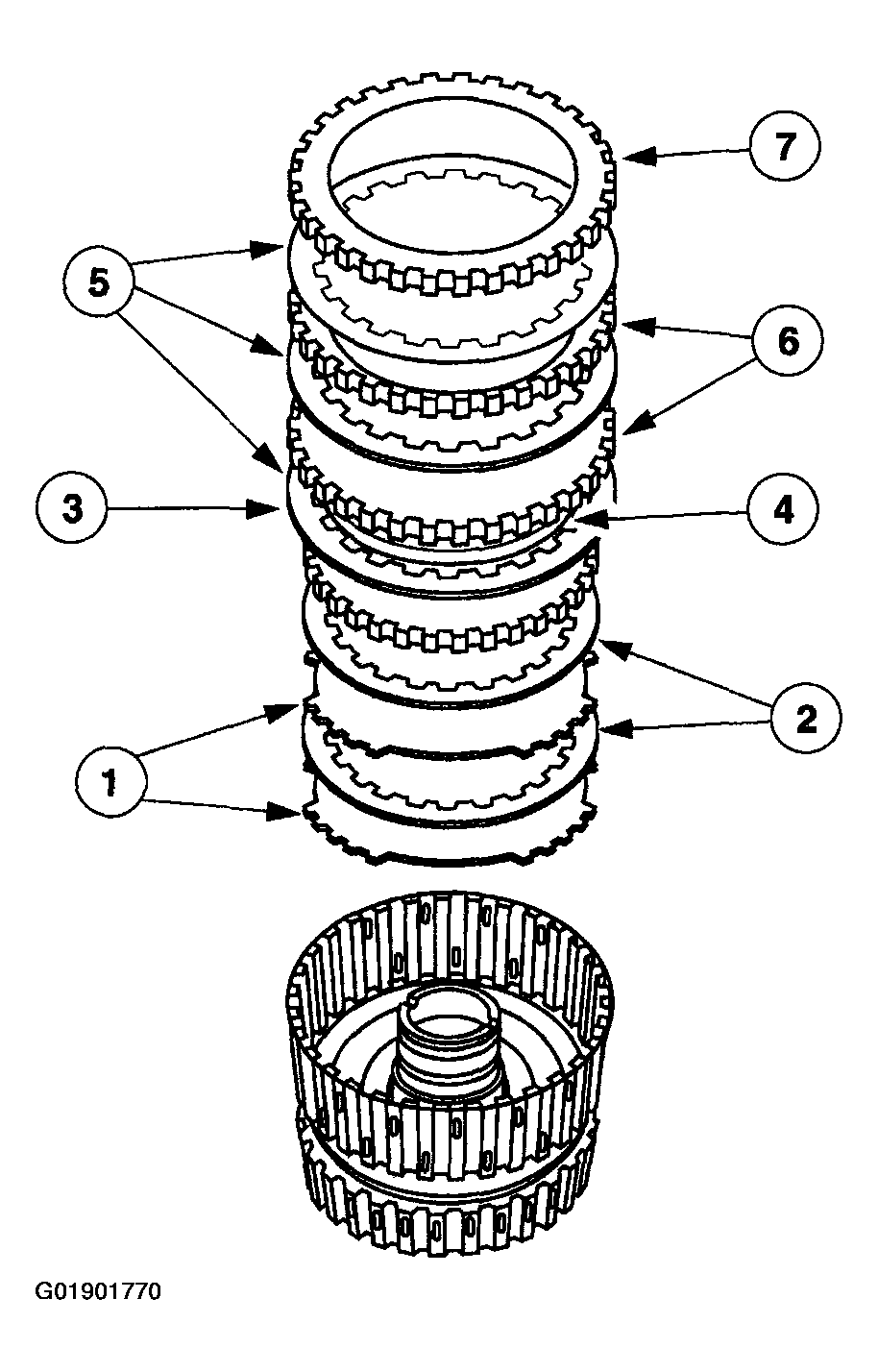 Courtesy of MAZDA MOTORS CORP.
- Install the forward and coast clutch plates in the sequence shown.
- Coast clutch external spline clutch plates (steel).
- Coast clutch internal spline clutch plates (friction).
- Coast clutch pressure plate.
- Forward clutch wave spring.
- Forward clutch internal spline clutch plates (friction).
- Forward clutch external spline clutch plates (steel).
- Forward clutch pressure plate.
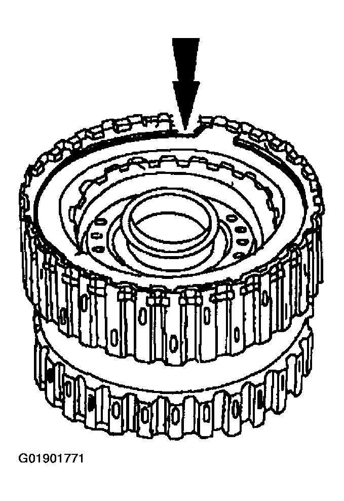 Courtesy of MAZDA MOTORS CORP.
- Install the forward clutch pressure plate retaining ring.
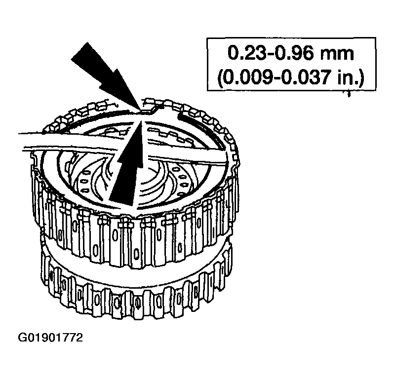 Courtesy of MAZDA MOTORS CORP.
- Using a feeler a gauge, measure the clearance between the forward clutch pressure plate and the forward clutch pressure plate retaining ring.
- Take a second measurement on the opposite side.
- Average the two measurements to get the clearance.
- If the clearance is not within specification, select and install the proper thickness retaining ring to obtain the standard clearance.
- Retaining ring sizes:
- 1.43-1.53 mm (0.056-0.060 in)
- 1.59-1.69 mm (0.062-0.066 in)
- 1.75-1.85 mm (0.069-0.073 in)
- 1.92-2.02 mm (0.075-0.079 in)
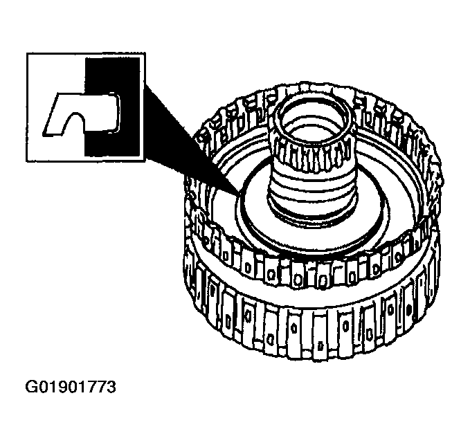 Courtesy of MAZDA MOTORS CORP.
- Install the direct clutch piston inner lip seal on the direct clutch cylinder assembly.
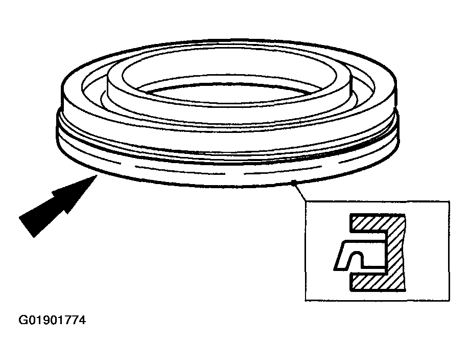 Courtesy of MAZDA MOTORS CORP.
- Install the direct clutch piston outer seal on the direct clutch piston assembly.
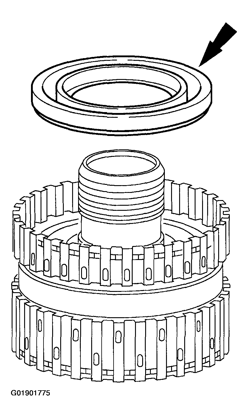 Courtesy of MAZDA MOTORS CORP.
NOTE:
- Position the lip seal facing down.
- Install the direct clutch piston assembly in the forward/coast/direct clutch cylinder assembly.
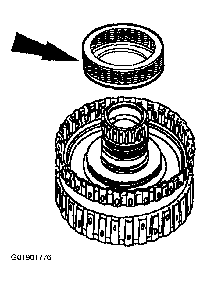 Courtesy of MAZDA MOTORS CORP.
- Install the direct clutch return spring assembly.
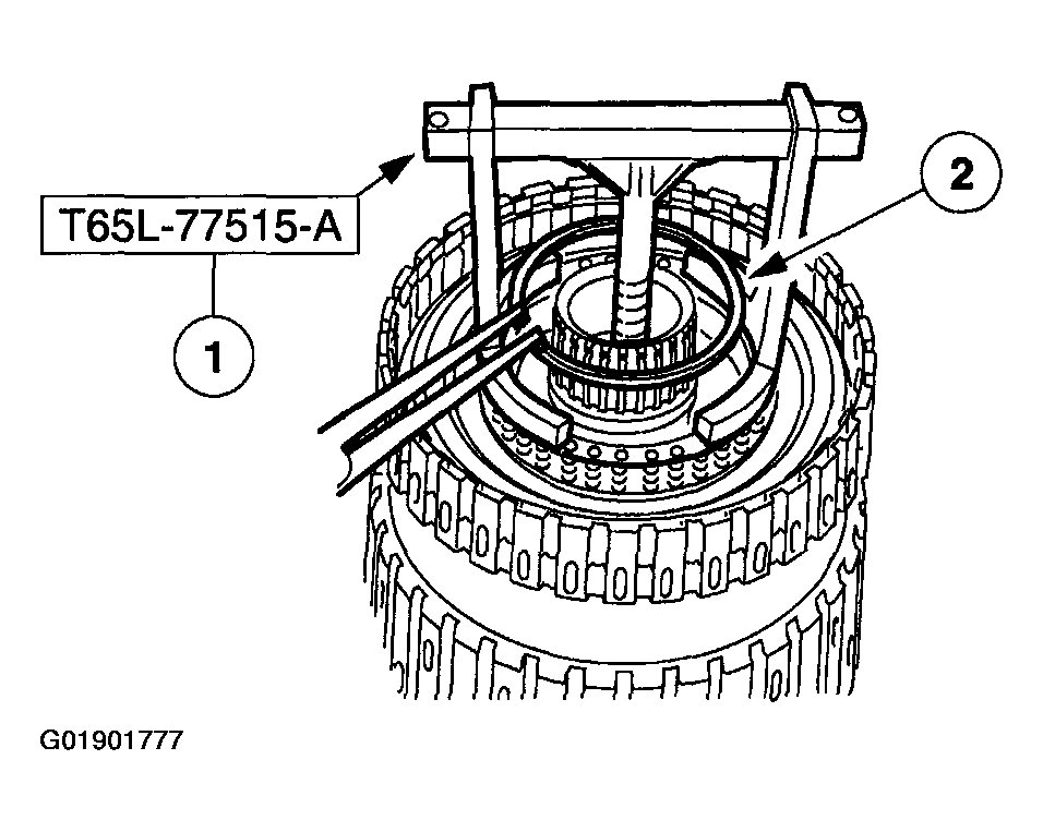 Courtesy of MAZDA MOTORS CORP.
WARNING:
- Use caution when releasing tool pressure on the clutch piston springs. Failure to follow these instructions can result in personal injury.
CAUTION:
- Do not compress the direct clutch return springs completely.
- Install the direct clutch return spring retaining ring.
- Using the special tool, compress the direct clutch return springs.
- Install the direct clutch return spring retaining ring.
 Courtesy of MAZDA MOTORS CORP.
NOTE:
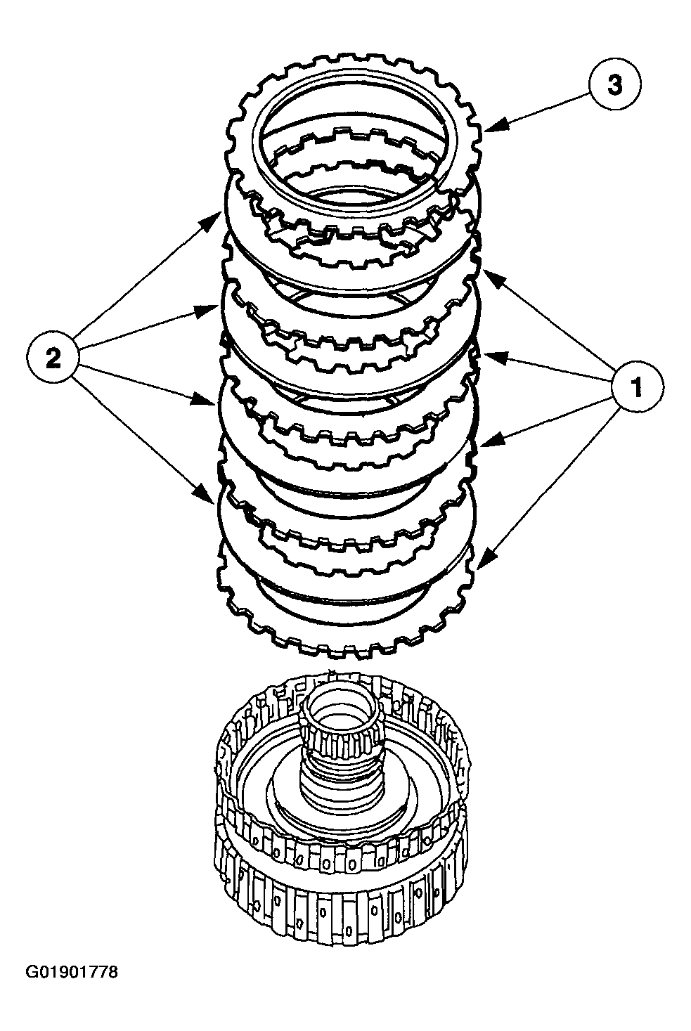
- Quantity of plates are model dependent.
- Install the direct clutch plates.
- Install the direct clutch external spline (steel) clutch plates.
- Install the direct clutch internal spline (friction) clutch plates.
- Install the direct clutch pressure plate.
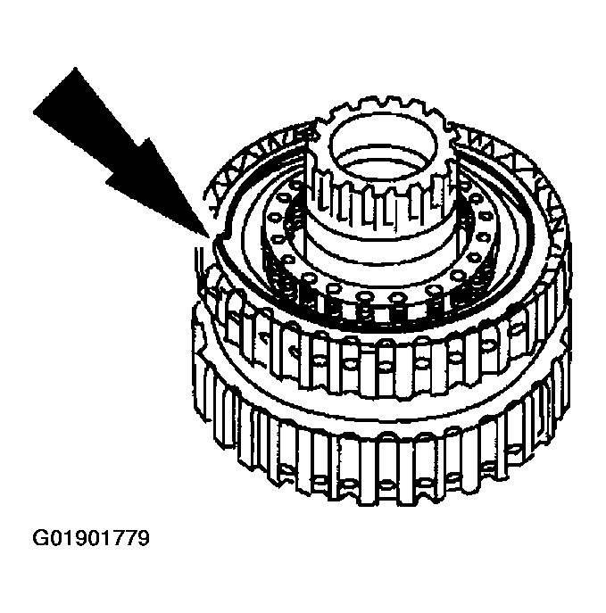 Courtesy of MAZDA MOTORS CORP.
- Install the direct clutch pressure plate retaining ring.
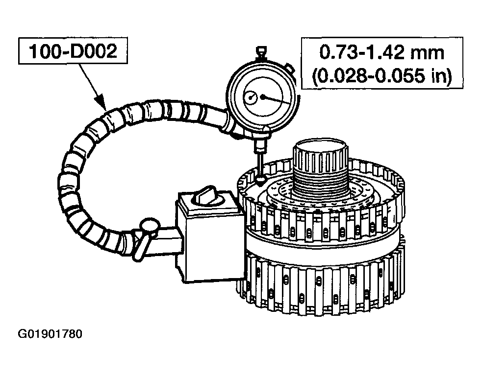 Courtesy of MAZDA MOTORS CORP.
- Measure the direct clutch clearance as follows:
- Install the special tool.
- Zero the dial on the direct clutch pressure plate.
- Pull the direct clutch pressure plate upward, and record the reading.
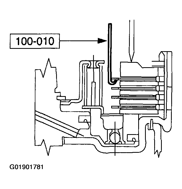 Courtesy of MAZDA MOTORS CORP.
- Make a second measurement on the opposite side. Average the two measurements to get the clearance. If the clearance is not within the specification, select and install, using the special tool, the correct thickness direct clutch pressure plate retainer snap ring to obtain the standard clearance.
- Retaining ring sizes:
- 1.28-1.38 mm (0.050-0.054 in)
- 1.39-1.49 mm (0.054-0.058 in)
- 1.52-1.62 mm (0.059-0.063 in)
- 1.65-1.75 mm (0.064-0.069 in)