Diagnostic Procedure
- Verify Related Repair Information Availability -
Turn ignition off. Connect scan tool to DLC-2. See Figure. Turn ignition on, engine off. Monitor for FREEZE FRAME DATA and ensure data has been recorded. Check service bulletins for repair information related to this DTC. If repair information is not available, go to next step. If repair information is available, perform diagnosis and repair as necessary. After repair, go to step 8.
- Inspect Brake Switch Signal Circuit For Short To Power -
Turn ignition off. Disconnect brake switch harness connector. See Fig 1. Turn ignition on, engine off. Measure voltage between ground and brake switch harness connector terminal "B" (Green wire). If battery voltage is not present, go to next step. If battery voltage is present, repair short circuit to voltage in Green wire between brake switch harness connector terminal "B" and PCM 31-pin harness connector terminal "4B". See appropriate WIRING DIAGRAM under ENGINE PERFORMANCE in SYSTEM WIRING DIAGRAMS. After repair, go to step 8.
- Inspect Brake Switch Connector For Poor Connection -
Turn ignition off. Check for poor connection at brake switch harness connector terminals due to damaged, pulled-out pins, corrosion, etc. If connector terminals are okay, go to next step. If connector terminals are found faulty, repair or replace as necessary. After repair, go to step 8.
- Inspect Brake Switch Power Circuit For Open -
Turn ignition on, engine off. Measure voltage between ground and brake switch harness connector terminal "A" (White/Green wire). If battery voltage is present, go to next step. If battery voltage is not present, repair open or short circuit in White/Green wire between engine compartment main fuse block and brake switch harness connector terminal "A". After repair, go to step 8.
- Inspect Poor Connection Of PCM Connector -
Turn ignition off. Disconnect PCM 31-pin harness connector. See Fig 1. Check for poor connection at PCM connector terminals due to damaged, pulled-out pins, corrosion, etc. If connector terminals are okay, go to next step. If connector terminals are found faulty, repair or replace as necessary. After repair, go to step 8.
- Inspect Brake Switch Signal Circuit For Open -
Reconnect brake switch harness connector. Turn ignition on, engine off. While depressing brake pedal measure voltage between ground and PCM 31-pin harness connector terminal "4B" (Green wire). If battery voltage is present, go to next step. If battery voltage is not present, repair open or short circuit in Green wire between brake switch harness connector terminal "B" and PCM 31-pin harness connector terminal "4B". After repair, go to step 8.
- Inspect Brake Switch -
Turn ignition off. Perform brake switch inspection. See BRAKELIGHT SWITCH
under ENGINE SENSORS & SWITCHES in SYSTEM & COMPONENT TESTING - MAZDA6, MIATA, MPV, PROTEGE & PROTEGE5 article. If brake switch is okay, go to next step. If brake switch is faulty, replace brake switch. After repair, go to next step.
- Verify Troubleshooting Of DTC P0703 Completed -
Return vehicle to original condition. Using scan tool, clear DTCs from PCM memory. See CLEARING DIAGNOSTIC TROUBLE CODES under SELF-DIAGNOSTIC SYSTEM. Start engine and let idle until normal operating temperature is reached. Drive vehicle at 18.6 MPH or more. Depress and release brake pedal 10 times or more during test drive. Monitor for DTCs. If same DTC is not present, go to next step. If same DTC P0703 is present, replace PCM. For PCM removal and installation, see POWERTRAIN CONTROL MODULE
under COMPUTERIZED ENGINE CONTROLS in REMOVAL, OVERHAUL & INSTALLATION article. After repair, go to next step.
- Verify After Repair Procedure -
Using scan tool, perform After Repair Procedure. See AFTER REPAIR PROCEDURE . If no other DTCs are present, testing is complete. If any other DTC is present, go to applicable test and repair.
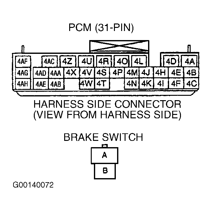 Courtesy of MAZDA MOTORS CORP.