Test 1: All Power Windows Inoperative
- Using NGS tester, retrieve and record continuous DTCs from GEM. Clear DTCs. Using NGS tester, perform on-demand self-test for GEM. If no DTCs exist, go to step 4. If DTCs B1302 or B1304 exist, go to next step.
- Turn ignition off. Disconnect accessory delay relay, located in Central Junction Box (CJB). Disconnect GEM harness connector T-201a. Turn ignition on. Measure voltage between ground and harness side of CJB accessory delay relay connector terminal No. 86. If voltage is detected, repair Light Blue/Red wire between CJB and GEM. See WIRING DIAGRAMS . If voltage is not detected, go to next step.
- Turn ignition off. Measure resistance of Light Blue/Red wire between accessory delay relay terminal No. 86 and GEM harness connector T-201a, terminal No. 17. See Fig 1. If resistance is less than 5 ohms, go to step 8. If resistance is 5 ohms or more, repair Light Blue/Red wire between accessory delay relay and GEM. See WIRING DIAGRAMS . Retest system.
- Turn ignition on. Disconnect accessory delay relay. Test accessory delay relay. See RELAYS under COMPONENT TESTS. If accessory delay relay is okay, go to next step. If accessory delay relay is defective, replace accessory delay relay. Clear DTCs and retest system operation.
- Turn ignition on. Disconnect GEM T-201a. Measure voltage between ground and harness side of CJB accessory relay connector terminal No. 85. If voltage is greater than 10 volts, go to next step. If resistance is less that 10 volts, repair open wire. See WIRING DIAGRAMS . Clear DTCs and retest system operation.
- Turn ignition off. Reconnect accessory delay relay. Disconnect power window main switch connector K-504. Turn ignition on. Measure voltage between ground and harness side of power window main switch K-504, terminal No. 8 (Red/Light Blue wire). See Fig 2. If measured voltage is greater than 10 volts, go to next step. If resistance is less than 10 volts, repair red/Light Blue wire between accessory delay relay and power window main switch. See WIRING DIAGRAMS . Retest system for normal operation.
- Turn ignition off. Measure resistance of Black wire between ground and power window main switch K-504, terminal No. 12. If resistance is less than 5 ohms, replace power window main switch. See MASTER WINDOW SWITCH under REMOVAL & INSTALLATION. If resistance is more than 5 ohms, repair Black wire between power window main switch K-504 and ground. See WIRING DIAGRAMS . Retest system for normal operation.
- Disconnect all GEM connectors. Check GEM connectors for corrosion or pushed out pins. Connect all GEM connectors and make sure they are connected correctly. Operate system and verify if concern is still present. If concern is still present, install new GEM. Clear DTCs and retest system operation. If concern is not present, system is operating correctly at this time. Concern may have been caused by loose or corroded pins. Clear DTCs and retest system operation.
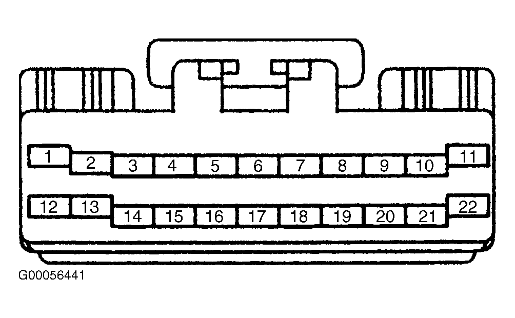 Courtesy of MAZDA MOTORS CORP.
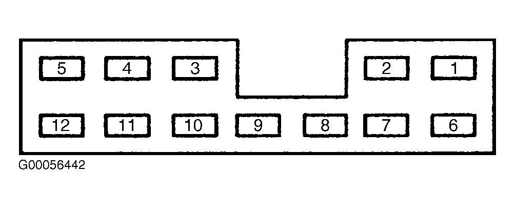 Courtesy of MAZDA MOTORS CORP.