Pinpoint Test L: DTC C1105
- L1 CHECK STOPLAMP OPERATION
- Press the brake pedal and verify the correct operation of the stoplamps.
- Are the stoplamps illuminated only when the brake pedal is pressed?
- L2 TEST THE STOPLAMP RELAY
- Disconnect: Adaptive Cruise Control Stoplamp Relay.
- Measure the resistance between Adaptive Cruise Control stoplamp relay pin-1 and pin-2, component side.
- Is the resistance between 63 and 120 ohms?
- Yes
: GO to L3.
- No
: INSTALL a new stoplamp relay. CLEAR the DTCs. REPEAT the self-test.
- L3 CHECK FOR VOLTAGE AT THE STOPLAMP RELAY CONTROL COIL
- Ignition ON.
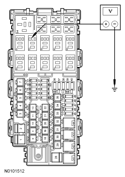
- Measure the voltage between stoplamp relay cavity 2, circuit CBP34 (VT/BN) and ground.
 Courtesy of FORD MOTOR CO.
- Is the voltage greater than 10 volts?
- Yes
: GO to L4.
- No
: VERIFY Battery Junction Box (BJB) fuse 13 (15A) is OK. If OK, REPAIR circuit CBP34 (VT/BN). If not OK, REFER to the SYSTEM WIRING DIAGRAMS
to identify the possible causes of the circuit short. CLEAR the DTCs. REPEAT the self-test.
- L4 CHECK THE STOPLAMP RELAY CONTROL GROUND CIRCUIT FOR AN OPEN
- Disconnect: ABS Module C135.
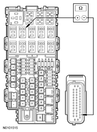
- Measure the resistance between stoplamp relay cavity 1, circuit CLS44 (VT/BN) and ABS module C135-36, circuit CLS44 (VT/BN), harness side.
 Courtesy of FORD MOTOR CO.
- Is the resistance less than 5 ohms?
- Yes
: GO to L5.
- No
: REPAIR circuit CLS44 (VT/BN). CLEAR the DTCs. REPEAT the self-test.
- L5 CHECK THE STOPLAMP RELAY CONTROL GROUND CIRCUIT FOR A SHORT TO GROUND
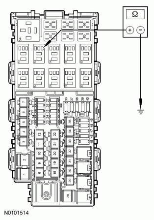
- Measure the resistance between stoplamp relay cavity 1, circuit CLS44 (VT/BN) and ground.
 Courtesy of FORD MOTOR CO.
- Is the resistance greater than 10, 000 ohms?
- Yes
: GO to L6.
- No
: REPAIR circuit CLS44 (VT/BN). CLEAR the DTCs. REPEAT the self-test.
- L6 CHECK THE STOPLAMP RELAY CONTROL GROUND CIRCUIT FOR A SHORT TO VOLTAGE
- Ignition ON.
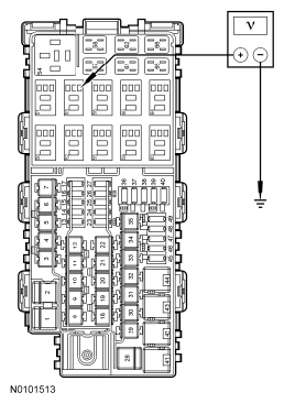
- Measure the voltage between stoplamp relay cavity 1, circuit CLS44 (VT/BN) and ground.
 Courtesy of FORD MOTOR CO.
- Is any voltage present?
- Yes
: REPAIR circuit CLS44 (VT/BN). CLEAR the DTCs. REPEAT the self-test.
- No
: GO to L7.
- L7 CHECK FOR CORRECT ABS MODULE OPERATION
- Disconnect: ABS Module C135.
- Check for:
- corrosion.
- pushed-out pins.
- spread terminals.
- Connect: ABS Module C135.
- Make sure that the connector is correctly seated.
- Connect the scan tool.
- Using the scan tool, clear all ABS module DTCs.
- Enter the following diagnostic mode on the scan tool: Self Test - ABS Module.
- Retrieve and record all ABS module DTCs.
- Is the DTC C1105 still present?
- Yes
: INSTALL a new ABS module. REFER to ANTI-LOCK BRAKE SYSTEM (ABS) MODULE . CLEAR the DTCs. CYCLE the ignition key. REPEAT the self-test.
- No
: The system is operating correctly at this time. The concern may have been caused by a loose or corroded connector.