Pinpoint Test C: The Transmission Control (TC) Switch Is Inoperative
- C1 CHECK FUSE F1.27
- Check fuse: Central Junction Box (CJB) Fuse F1.27 (5A).
- Is the resistance less than 5 ohms?
- Yes
: GO to C3.
- No
: INSTALL a new fuse. TEST the system for normal operation. If the fuse fails again, GO to C2.
- C2 CHECK CIRCUIT 1003 (GY/YE) FOR A SHORT TO GROUND
- Disconnect: Central Junction Box (CJB) Fuse F1.27 (5A).
- Measure the resistance between output side of fuse F1.27 (5A) and ground.
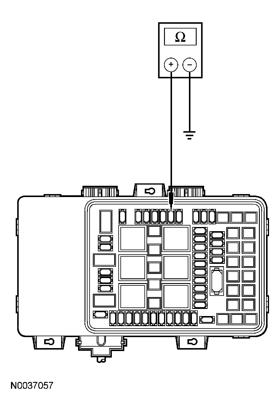 Courtesy of FORD MOTOR CO.
- Is the resistance greater than 10,000 ohms?
- Yes
: GO to C4.
- No
: REPAIR circuit 1003 (GY/YE) for a short to ground.
- C3 CHECK CIRCUIT 1003 (GY/YE) FOR AN OPEN
- Disconnect: Central Junction Box Fuse F1.27 (5A).
- Disconnect: Selector Lever C2135.
- Measure the resistance between selector lever C2135-B and output side of CJB fuse F1.27.
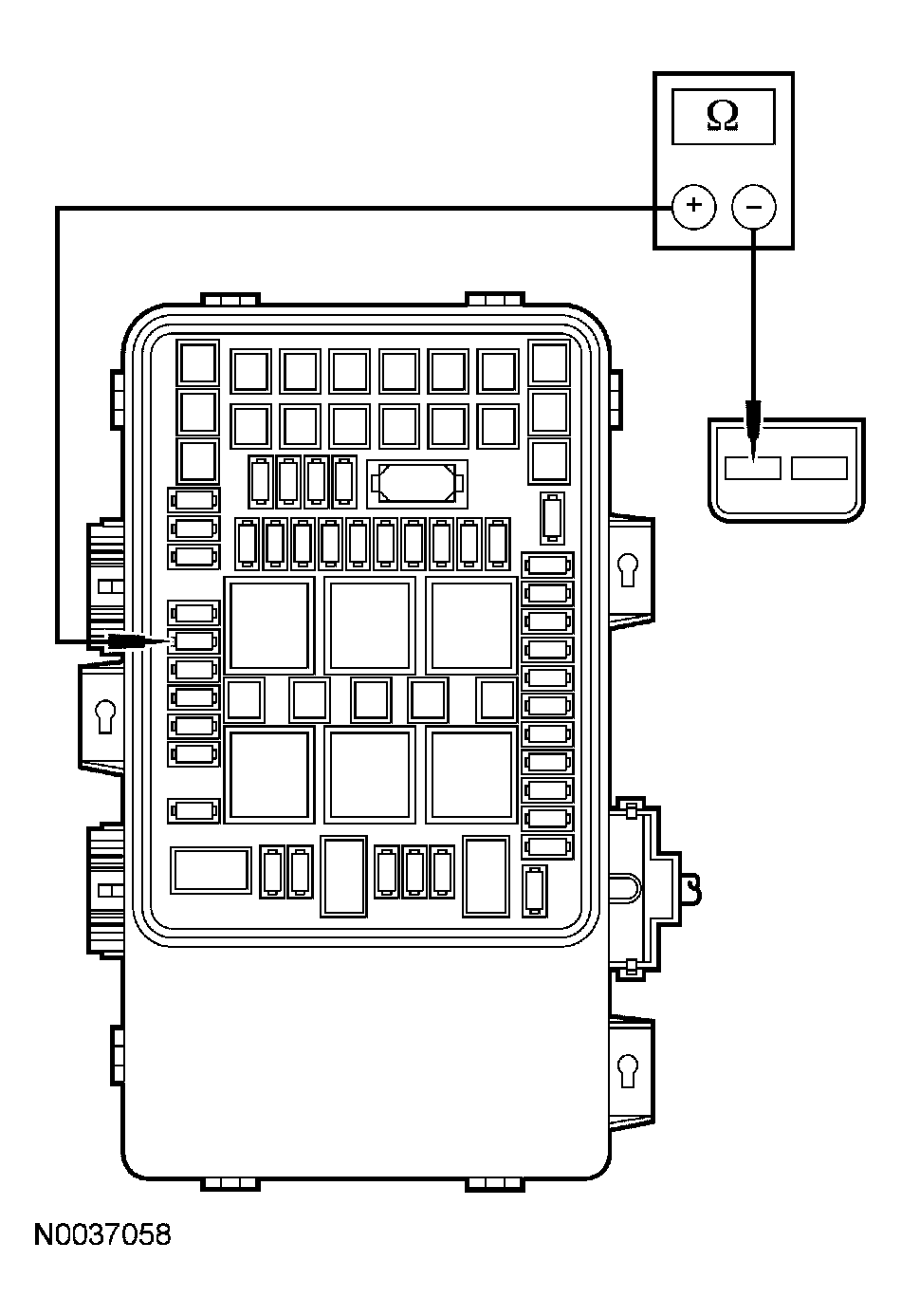 Courtesy of FORD MOTOR CO.
- Is the resistance less than 5 ohms?
- Yes
: GO to C6.
- No
: REPAIR circuit 1003 (GY/YE). RECONNECT all components. TEST the system for normal operation.
- C4 CHECK TRANSMISSION CONTROL (TC) SWITCH FOR A SHORT TO GROUND
- Disconnect: Selector Lever C2135.
- Measure the resistance between selector lever C2135-A and ground while cycling the TC switch.
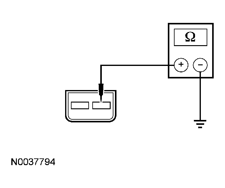 Courtesy of FORD MOTOR CO.
- Is the resistance greater than 10,000 ohms?
- Yes
: GO to C5.
- No
: INSTALL a new transmission selector lever. RECONNECT all components. TEST the system for normal operation.
- C5 CHECK CIRCUIT 224 (TN/WH) FOR A SHORT TO GROUND
- Disconnect: Powertrain Control Module C175b.
- Inspect for damaged or pushed-out pins, corrosion or loose wires. Repair as necessary.
- Measure the resistance between circuit 224 (TN/WH), powertrain control module C175b-45 and ground.
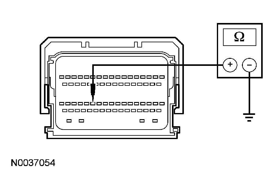 Courtesy of FORD MOTOR CO.
- Is the resistance greater than 10,000 ohms?
- Yes
: INSTALL a new PCM. RECONNECT all components. TEST the system for normal operation.
- No
: REPAIR circuit 224 (TN/WH). RECONNECT all components. TEST the system for normal operation.
- C6 TEST CIRCUIT 224 (TN/WH) FOR OPEN
- Disconnect: Powertrain Control Module C175b..
- Measure the resistance between selector lever C2135-A and PCM C175b-45.
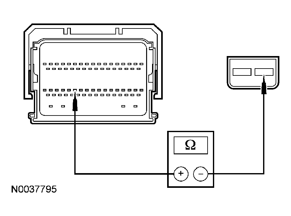 Courtesy of FORD MOTOR CO.
- Is the resistance less than 5 ohms?
- Yes
: GO to C7.
- No
: REPAIR circuit 224 (TN/WH). RECONNECT all components. TEST the system for normal operation.
- C7 TEST THE TC SWITCH FOR NORMAL OPERATION
- Measure the resistance between selector lever C2135-A and C2135-B while cycling the TC switch.
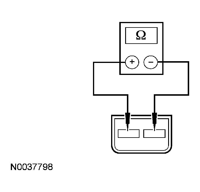 Courtesy of FORD MOTOR CO.
- Is the resistance less than 5 ohms while pressed and greater than 10 k ohms when released?
- Yes
: INSTALL a new PCM. RECONNECT all components. TEST the system for normal operation.
- No
: INSTALL a new transmission selector lever. RECONNECT all components. TEST the system for normal operation.