Radio Receiver: Installation: Installation
- INSTALL RADIO RECEIVER ASSEMBLY (w/o Navigation System)
- Install the radio receiver assembly as shown in the illustration.
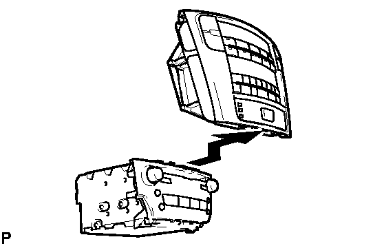 Courtesy of © TOYOTA, LICENSE AGREEMENT TMS1002
- INSTALL NO. 2 RADIO BRACKET (w/o Navigation System)
- Engage the guide and install the No. 2 radio bracket with the 6 bolts.
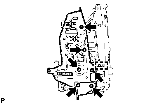 Courtesy of © TOYOTA, LICENSE AGREEMENT TMS1002
- INSTALL NO. 1 RADIO BRACKET (w/o Navigation System)
- Engage the guide and install the No. 1 radio bracket with the 6 bolts.
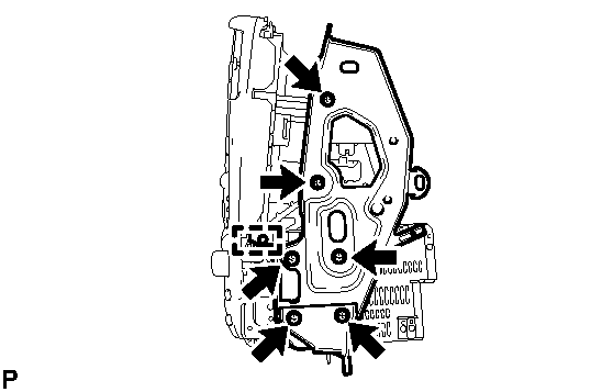 Courtesy of © TOYOTA, LICENSE AGREEMENT TMS1002
- INSTALL INTEGRATION CONTROL PANEL WITH RADIO RECEIVER ASSEMBLY (w/o Navigation System)
- Connect each connector.
- Install the integration control panel with radio receiver assembly with the 4 bolts.
- INSTALL RADIO RECEIVER ASSEMBLY (w/ Navigation System)
- Install the radio receiver assembly as shown in the illustration.
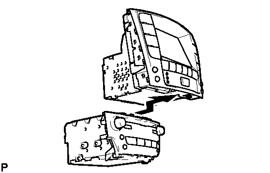 Courtesy of © TOYOTA, LICENSE AGREEMENT TMS1002
- INSTALL NO. 2 RADIO BRACKET (w/ Navigation System)
- Engage the guide and install the No. 2 radio bracket with the 7 bolts.
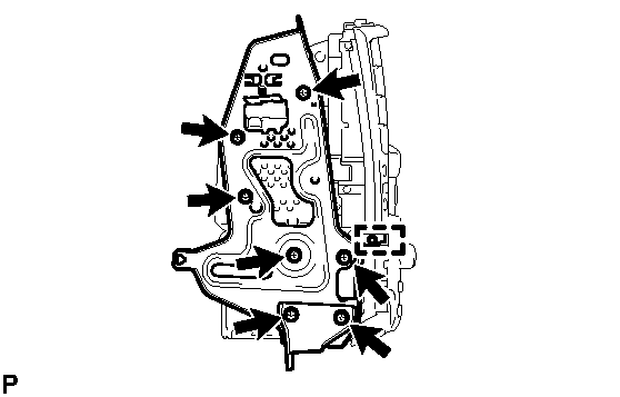 Courtesy of © TOYOTA, LICENSE AGREEMENT TMS1002
- INSTALL NO. 1 RADIO BRACKET (w/ Navigation System)
- Engage the guide and install the No. 1 radio bracket with the 7 bolts.
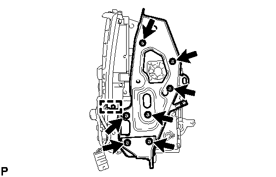 Courtesy of © TOYOTA, LICENSE AGREEMENT TMS1002
- Engage the connector clamp.
- INSTALL DISPLAY AND NAVIGATION MODULE DISPLAY WITH RADIO RECEIVER ASSEMBLY (w/ Navigation System)
- Connect each connector.
- Install the display and navigation module display with radio receiver assembly with the 4 bolts.
- INSTALL CENTER LOWER INSTRUMENT CLUSTER FINISH PANEL
. Refer to INSTALLATION - Step 41
- INSTALL NO. 3 INSTRUMENT PANEL REGISTER ASSEMBLY
. Refer to INSTALLATION - Step 42
- INSTALL FRONT ASH RECEPTACLE BOX SUB-ASSEMBLY (w/ Ashtray)
. Refer to INSTALLATION - Step 46
- INSTALL INSTRUMENT PANEL BOX ASSEMBLY (w/o Ashtray)
. Refer to INSTALLATION - Step 47
- INSTALL FRONT CONSOLE PANEL SUB-ASSEMBLY (for Manual Transmission)
. Refer to INSTALLATION - Step 48
- INSTALL REAR CONSOLE PANEL SUB-ASSEMBLY (for Manual Transmission)
. Refer to INSTALLATION - Step 49
- INSTALL CONSOLE PANEL SUB-ASSEMBLY (for Automatic Transmission)
. Refer to INSTALLATION - Step 50
- INSTALL UPPER NO. 1 CONSOLE PANEL GARNISH (for Automatic Transmission)
. Refer to INSTALLATION - Step 52
- INSTALL UPPER NO. 2 CONSOLE PANEL GARNISH (for Automatic Transmission)
. Refer to INSTALLATION - Step 51
- INSTALL SHIFT LEVER KNOB SUB-ASSEMBLY (for Manual Transmission)
- INSTALL SHIFT LEVER KNOB SUB-ASSEMBLY (for Automatic Transmission)
- CONNECT CABLE TO NEGATIVE BATTERY TERMINAL
- ADJUST CLOCK