Vehicle Speed Sensor (VSS) No. 1 Circuit (Speedometer Does Not Operate)
- If odometer does not operate, go to next step. If odometer operates, check trip meter operation. If trip meter does not operate, go to step 4). If trip meter operates, replace speedometer.
- Remove instrument cluster, leaving electrical connectors attached. Raise and support vehicle with rear wheels off of ground. Turn ignition on. At instrument cluster 23-pin connector, connect voltmeter between terminals No. 13 (Blue/Red wire) and No. 14 (Red wire). See Figure. Rotate drive shaft.
- If voltage alternates between zero and 11 or more volts for each revolution of drive shaft, replace printed circuit plate. If voltage does not alternate between zero and 11 or more volts, check VSS No. 1. See VEHICLE SPEED SENSOR (VSS) NO. 1. Replace sensor as necessary. If VSS No. 1 is okay, repair circuit between VSS No. 1 and instrument cluster.
- Remove instrument cluster, leaving all connectors attached except 23-pin connector. At 23-pin connector (harness side), connect one end of a jumper wire to terminal No. 2 (Orange wire. Connect other end of jumper wire to corresponding terminal on instrument cluster. Use same procedure for the following terminals. This simulates an attached 23-pin connector, but with only 4 wires connected.
- No. 13 (Blue/Red wire).
- No. 14 (Red wire).
- No. 23 (White/Black wire).
- Raise and support vehicle with rear wheels off of ground. Turn ignition on. Connect voltmeter between terminals No. 13 and 14 of 23-pin connector. See Figure. Rotate drive shaft. If voltage alternates between zero and 11 or more volts for each revolution of drive shaft, replace speedometer and retest. If voltage does not alternate between zero and 11 or more volts, replace printed circuit plate and retest. See Fig 1.
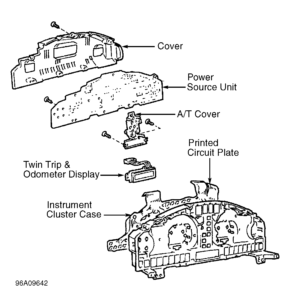 Courtesy of © TOYOTA, LICENSE AGREEMENT TMS1002