Diagnosis & Repair (Using OBD-II Scan Tool)
- Check EVAP VSV, vapor pressure sensor VSV and vapor pressure sensor wiring harness connectors for damaged pins, corrosion and loose wires. Repair as necessary. If connectors are okay, go to next step. For component locations, see appropriate illustration in the THEORY/OPERATION
article.
- Check all EVAP related vacuum hoses for cracks, looseness and correct routing. Repair as necessary. If vacuum hoses are okay, go to next step. For proper vacuum hose routing, see VACUUM DIAGRAMS
article.
- Access ECM harness connectors behind glove box. Turn ignition on. Backprobing ECM harness connector, measure voltage between terminals No. 1 (Blue/Red wire) and No. 22 (Brown wire) at ECM E13 connector. See Figure. If voltage is 4.5-5.5 volts, go to next step. If voltage is not 4.5-5.5 volts, replace ECM and retest.
- Backprobing ECM harness connector, measure voltage between terminals No. 18 (Pink/Green wire) at ECM E11 connector and No. 22 (Brown wire) at ECM E13 connector. Disconnect vacuum hose from vapor pressure sensor. Sensor is mounted on top of charcoal canister and is located in left front of engine compartment. Connect a vacuum pump to sensor. If voltage is 3.0-3.7 volts without vacuum applied and .5 volt or less with 1.2-19.7 in. Hg (8-135 kPa) applied, go to step 6). If voltage is not as specified, go to next step.
- Check for an open or short in wiring harness between vapor pressure sensor and ECM. Refer to the appropriate wiring diagram in the WIRING DIAGRAMS
article. Repair as necessary. If wiring is okay, replace vapor pressure sensor.
- Disconnect EVAP VSV vacuum hoses. For VSV location, see the VACUUM DIAGRAMS
article. Apply air pressure to VSV port "E". See Fig 1. Air should not flow from port "F". Access ECM harness connectors behind glove box. Turn ignition on. Connect jumper wire between ground and terminal No. 8 (Blue/Black wire) at ECM E12 connector. See Figure. Air should flow from port "F". If VSV functions as specified, g o to step 9). If VSV does not function as specified, go to next step.
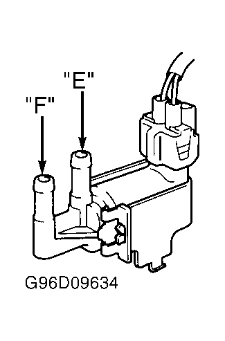 Courtesy of © TOYOTA, LICENSE AGREEMENT TMS1002
- Check EVAP VSV. See EMISSION SYSTEMS & SUB-SYSTEMS in the SYSTEM/COMPONENT TESTS
article. Replace VSV as necessary. If VSV is okay, go to next step.
- Check for an open or short in wiring harness between EFI main relay, EVAP VSV and ECM. Refer to appropriate wiring diagram in the WIRING DIAGRAMS
article. Repair as necessary. If wiring is okay, replace ECM and retest.
- Disconnect vapor pressure sensor VSV vacuum hoses. VSV is mounted on top of EVAP charcoal canister. Apply air pressure to VSV port "E". See Fig 2. Air should flow from port "G". Access ECM harness connectors behind glove box. Turn ignition on. Connect jumper wire between ground and terminal No. 17 (Violet/Green wire) at ECM E11 connector. See Figure. Air should flow from port "F". If VSV does not function as specified, go to next step. If VSV functions as specified, check charcoal canister. Refer to EMISSION SYSTEMS & SUB-SYSTEMS in the SYSTEM/COMPONENT TESTS
article. Replace canister as necessary.
- Check vapor pressure sensor VSV. See EMISSION SYSTEMS & SUB-SYSTEMS in SYSTEM/COMPONENT TESTS
article. Replace VSV as necessary. If VSV is okay, go to next step.
- Check for an open or short in wiring harness between EFI main relay, vapor pressure sensor VSV and ECM. See appropriate wiring diagram in WIRING DIAGRAMS
article. Repair as necessary. If wiring is okay, replace ECM and retest.
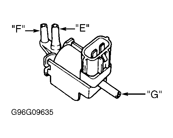 Courtesy of © TOYOTA, LICENSE AGREEMENT TMS1002