Vehicle Speed Sensor (VSS) No. 1 Circuit (Speedometer Does Not Operate)
- Remove instrument cluster, but leave electrical connectors attached. Raise and support vehicle with rear wheels off of ground. Turn ignition on. Connect voltmeter between chassis ground and terminal No. 8 (Yellow wire) of instrument cluster 22-pin Gray connector. Rotate drive shaft.
- If voltage does not alternate between zero and 12 volts or more for each revolution of drive shaft, go to next step. If voltage alternates between zero and 12 volts or more, replace ECM and retest.
- Remove cover and power source unit from back of instrument cluster for access to printed circuit. Check for continuity between the following speedometer terminals of printed circuit. See Fig 1. If continuity does not exist, replace printed circuit. If continuity exists, go to next step.
- "A" and b6.
- "B" and a15.
- "C" and b5.
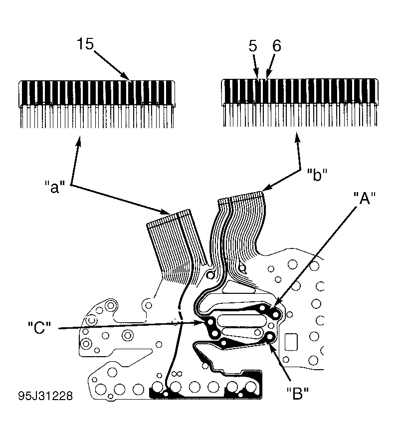 Courtesy of © TOYOTA, LICENSE AGREEMENT TMS1002
- Check VSS. See VEHICLE SPEED SENSOR (VSS) NO . 1. Replace VSS as necessary and recheck system. If VSS is okay, access ECM behind glove box. Disconnect ECM connectors. Check continuity of Yellow wire between terminal No. 12 at ECM E11 connector and instrument cluster 22-pin Gray connector. To identify ECM connectors and terminals, see Figure. If continuity exists, go to next step. If continuity does not exist, locate and repair open in Yellow wire.
- Check continuity of Red wire between terminal No. 4 at ECM E13 connector and VSS connector. If continuity exists, go to next step. If continuity does not exist, locate and repair open in Red wire.
- Check continuity of Green wire between terminal No. 9 at ECM E13 connector and VSS connector. If continuity exists, replace power source unit and retest. If continuity does not exist, locate and repair open in Green wire.