CROSSMEMBER, Rear Suspension: Installation: Installation
 Courtesy of CHRYSLER GROUP, LLC
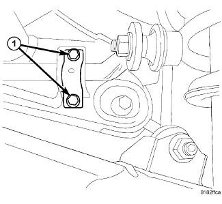
- Install the stabilizer bar and install the bushings and bolts (1).
- Tighten the bolts to 61 N.m (45 ft. lbs.).
 Courtesy of CHRYSLER GROUP, LLC
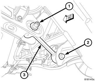
- Position the suspension knuckle assemblies back into position onto the crossmember.
- Install the toe link cam bolts (1) at the cradle.
- Tighten the bolts to 35 N.m (26 ft. lbs.).
 Courtesy of CHRYSLER GROUP, LLC
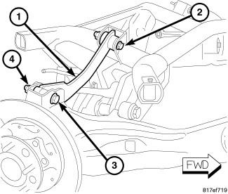
- Install the upper link bolts (2) at the cradle.
- Tighten the bolts to 90 N.m (70 ft. lbs.).
 Courtesy of CHRYSLER GROUP, LLC
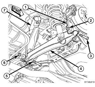
- Install the lower link bolts (5 and 6) at the cradle.
- Tighten the bolts to 90 N.m (70 ft. lbs.).
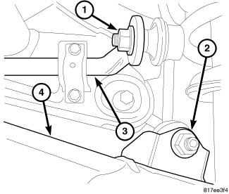 Courtesy of CHRYSLER GROUP, LLC
- Install the stabilizer link nuts (2).
- Tighten the nuts to 58 N.m (43 ft. lbs.).
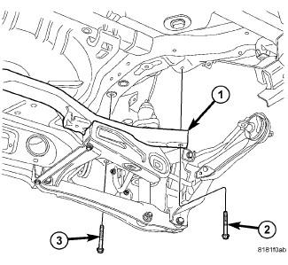 Courtesy of CHRYSLER GROUP, LLC
- Support the rear cradle assembly (1) with a suitable lifting device and position back into the vehicle.
- Install the cradle bolts (2 and 3):
- Tighten the front bolt (2) first to 110 N.m (81 ft. lbs.).
- Tighten the rear bolt (3) next to 110 N.m (81 ft. lbs.).
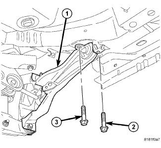 Courtesy of CHRYSLER GROUP, LLC
- Install the trailing link (1) bushing bolts (2 and 3):
- Tighten the inboard bolt (3) first to 110 N.m (81 ft. lbs.).
- Tighten the outboard bolt (2) next to 110 N.m (81 ft. lbs.).
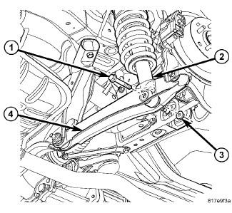 Courtesy of CHRYSLER GROUP, LLC
- Install the lower strut bolts (1).
- Tighten the bolts to 99 N.m 73 ft. lbs.).
 Courtesy of CHRYSLER GROUP, LLC
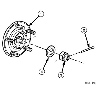
- If equipped, install the rear half shafts.
- Install the nuts (3) and washers (4).
- Tighten the nuts to 244 N.m (180 ft. lbs.).
- Install new cotter pins (2).
 Courtesy of CHRYSLER GROUP, LLC
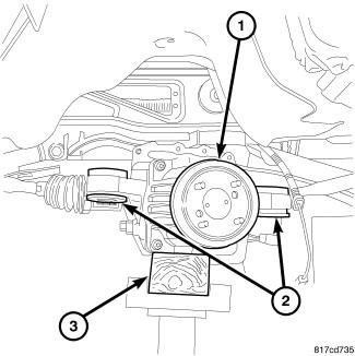
- Install the rear drive module (1). Refer to INSTALLATION
.
- Install the wheel speed sensor back. Refer to SENSOR, WHEEL SPEED, REAR, INSTALLATION
.
 Courtesy of CHRYSLER GROUP, LLC
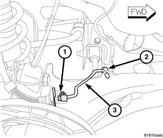
- Position the brake lines (3) back into place, connect the clips (2) and install the bolts (1).
- Tighten the bolts to 15 N.m (11 ft. lbs.).
 Courtesy of CHRYSLER GROUP, LLC
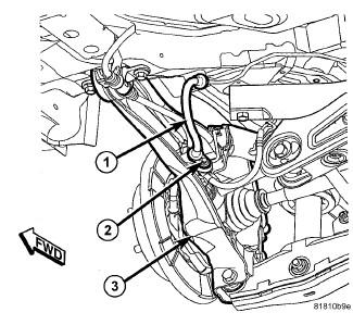
- Position the brake lines (1) back into place, and install the bolts (2).
- Tighten the bolts to 23 N.m (17 ft. lbs.).
 Courtesy of CHRYSLER GROUP, LLC
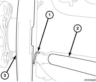
- Install the brake cable (2) onto the backing plate (3) and install the hair pin clip (1).
 Courtesy of CHRYSLER GROUP, LLC
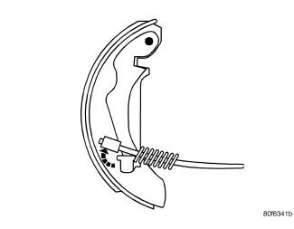
- Connect the brake cable to the park brake lever.
- Install the park brake shoes. Refer to SHOES, PARKING BRAKE, INSTALLATION
.
- Check and adjust wheel alignment as necessary. Refer to WHEEL ALIGNMENT, STANDARD PROCEDURE
.