Power Transfer Unit (Service Information): Removal: Removal
 Courtesy of CHRYSLER LLC
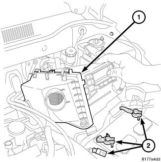
- Disconnect negative battery cable (2).
- Remove the engine trim cover.
- Remove air cleaner assembly (1).
- Remove Power Distribution Center (PDC) from bracket.
- Raise the vehicle on the hoist.
- Remove front halfshafts. Refer to Removal
.
 Courtesy of CHRYSLER LLC
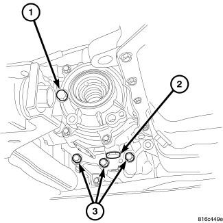
- Remove drain plug (2) at PTU and allow fluid to drain.
- Reinstall drain plug.
 Courtesy of CHRYSLER LLC
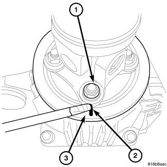
- Mark (2) prop shaft and differential (3) for proper installation.
- Remove the rear prop shaft. Refer to Removal
.
 Courtesy of CHRYSLER LLC
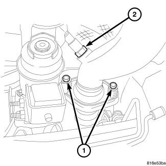
- Remove the two exhaust to maniverter (exhaust manifold with catalytic converter) bolts (1).
- Unplug the downstream O2 sensor connector.
- Remove the exhaust system. Refer to MUFFLER, Exhaust, Removal
.
- Lower the vehicle on the hoist.
- Unplug the upstream O2 sensor connector.
 Courtesy of CHRYSLER LLC
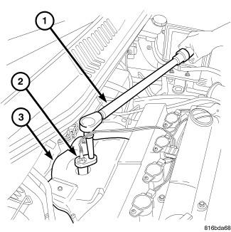
- Remove upstream O2 sensor from the maniverter (exhaust manifold with catalytic converter) using O2s (Oxygen Sensor) Remover/Installer (special tool #8439, O2 Sensor Wrench) (2).
 Courtesy of CHRYSLER LLC
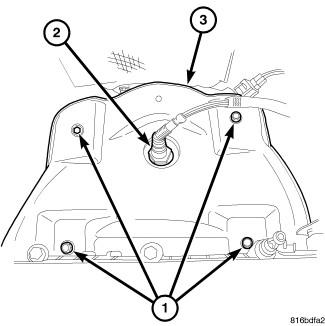
- Remove the four maniverter heat shield bolts (1).
 Courtesy of CHRYSLER LLC
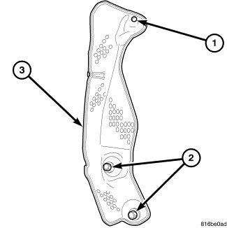
- Remove the two retaining bolts (2) and one nut (1) from the maniverter side heat shield (3).
 Courtesy of CHRYSLER LLC
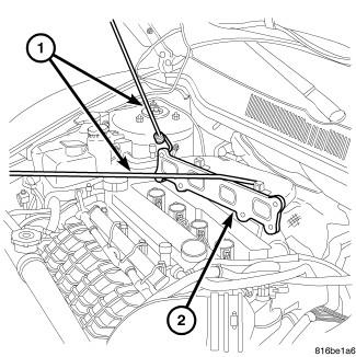
- Remove the seven maniverter to head retaining bolts.
- Slide the maniverter up and to the right, support the maniverter (1) with the help of a bungie cord.
 Courtesy of CHRYSLER LLC
- Raise the vehicle on the hoist.
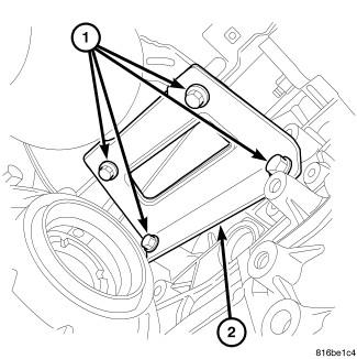
- Remove the four (1) engine to maniverter bracket bolts.
 Courtesy of CHRYSLER LLC
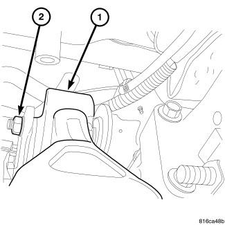
- Remove the rear engine mount through bolt (2).
- Remove the three front engine mount to frame bolts and the mount through bolt.
 Courtesy of CHRYSLER LLC
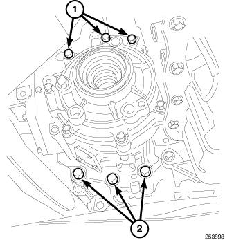
- Remove the PTU mounting bolts (1, 2).
 Courtesy of CHRYSLER LLC
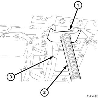
- Install a screw jack (2) on front engine mount bracket (1).
 Courtesy of CHRYSLER LLC
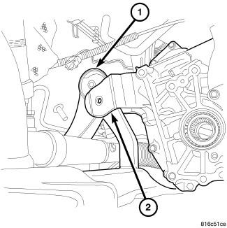
- Raise the front of the engine until the rear mount has dropped (1, 2).
- Separate the PTU from the transaxle.
- Remove and discard old O-ring between Transmission and PTU.
 Courtesy of CHRYSLER LLC
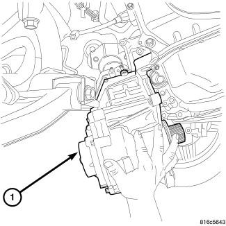
- Roll the PTU (1) forward and down to remove.