No Response From Controller Anti-Lock Brake (CAB)
- Turn ignition on. Using scan tool, attempt to communicate with Air Bag Control Module (ACM) and Body Control Module (BCM). If scan tool can identify or establish communications with ACM or BCM, go to next step. If scan tool cannot identify or establish communications with ACM or BCM, go to PCI BUS COMMUNICATIONS FAILURE . Perform ABS VERIFICATION TEST under VERIFICATION TESTS.
- Turn ignition off. Remove and inspect fuse No. 19 (10-amp) located in junction block. Junction block is located between battery and right front fender. If fuse is blown, go to next step. If fuse is okay, go to step 6.
- Install new fuse. Turn ignition on. Recheck condition of fuse No. 19. If fuse is blown, go to next step. If fuse is okay, repair short to ground in Dark Blue/Pink wire between CAB and junction block. Perform ABS VERIFICATION TEST under VERIFICATION TESTS.
- Turn ignition off. Replace fuse No. 19. Disconnect CAB connector. See Figure. Turn ignition on. Recheck condition of fuse No. 19. If fuse is blown, go to next step. If fuse is okay, replace CAB. See CONTROLLER ANTI-LOCK BRAKE under REMOVAL & INSTALLATION. Perform ABS VERIFICATION TEST under VERIFICATION TESTS.
- Turn ignition off. Disconnect junction block connectors. See Figure. Using DVOM, measure resistance between ground and junction block connector C2 terminal No. 42 (Dark Blue/Pink wire). See Figure. If resistance is less than 5 ohms, repair short to ground in Dark Blue/Pink wire between CAB and junction block. Perform ABS VERIFICATION TEST under VERIFICATION TESTS. If resistance is greater than 5 ohms, replace junction block. Perform ABS VERIFICATION TEST under VERIFICATION TESTS.
- Turn ignition off. Ensure fuse No. 19 is installed in junction block. Disconnect CAB connector. See Figure. Turn ignition on. Using DVOM, measure voltage between ground and CAB connector terminal No. 4 (Dark Blue/Pink wire). See Fig 1. If voltage is greater than 10 volts, go to next step. If voltage is less than 10 volts, repair open in Dark Blue/Pink wire between CAB and junction block. Perform ABS VERIFICATION TEST under VERIFICATION TESTS.
- Using DVOM, measure resistance between ground and CAB connector terminals No. 8 (Black/Orange wire) and 24 (Black/Orange wire). If resistance is less than 5 ohms at both terminals, go to next step. If resistance is greater than 5 ohms, repair open in appropriate Black/Orange wire between CAB and ground. Perform ABS VERIFICATION TEST under VERIFICATION TESTS.
- Use Scope Input Cable (CH7058), Cable-To-Probe Adapter (CH7062) and Red and Black test probes. Connect scope input cable to channel one connector on scan tool. Attach Red and Black test probes and cable-to-probe adapter to scope input cable. Select scan tool STANDALONE function. Select LAB SCOPE. Select LIVE. Select 12 VOLT SQUARE WAVE. Press F2 for scope display. Press F2 and use down arrow to select voltage range to 20 volts. Press F2 after selecting 20 volts. Connect Black test probe lead to ground and Red test probe lead to CAB connector terminal No. 10 (Yellow/Violet wire). Turn ignition on. Observe voltage readings on scan tool. If reading pulses from zero to approximately 7.5 volts, go to next step. If reading is steady at zero volts, repair PCI bus circuit (Yellow/Violet wire) between CAB and diagnostic junction port. See appropriate wiring diagram in DATA LINK CONNECTORS article in WIRING DIAGRAMS. Perform ABS VERIFICATION TEST under VERIFICATION TESTS.
- Replace CAB. See CONTROLLER ANTI-LOCK BRAKE under REMOVAL & INSTALLATION. Perform ABS VERIFICATION TEST under VERIFICATION TESTS.
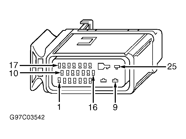 Courtesy of CHRYSLER CORP.