No PCI Messages From CD Changer
- Turn ignition off. Disconnect Black 7-pin cable connector from radio and CD changer. Visually inspect cable for damage at radio and CD changer end. Resistance should be present between each matching terminals. Using DVOM, measure resistance between each terminal at each end of cable. Using DVOM, measure resistance between each terminal and metal connector sleeve. See Fig 1 Resistance should not be present. If resistance is as specified, go to next step. If resistance is not as specified, replace cable. Perform BODY VERIFICATION TEST under VERIFICATION TESTS.
- Connect cable to radio. Use Scope Input Cable (CH7058), Cable-To-Probe Adapter (CH7062) and Red and Black test probes. Connect scope input cable to channel one connector on scan tool. Attach Red and Black test probes and cable-to-probe adapter to scope input cable. Select scan tool STANDALONE function. Select LAB SCOPE. Select LIVE. Select 12 VOLT SQUARE WAVE. Press F2 for scope display. Press F2 and use down arrow to select voltage range to 20 volts. Press F2 after selecting 20 volts. Connect Black test probe lead to ground and Red test probe lead to cable connector terminal No. 3 (Yellow/Violet wire) at CD changer. Turn ignition on and turn radio/CD changer on. Observe voltage readings on scan tool. If reading pulses from zero to approximately 7.5 volts, go to next step. If reading is steady at zero volts, repair PCI bus circuit (Yellow/Violet wire) between radio and CD changer. See appropriate wiring diagram in DATA LINK CONNECTORS article in WIRING DIAGRAMS. Perform BODY VERIFICATION TEST under VERIFICATION TESTS.
- Disconnect test probe leads. With ignition on, ensure radio and CD changer are on. Using DVOM, measure voltage between ground and cable connector terminal No. 4 (Red wire) at CD changer. If voltage is greater than 10.5 volts, go to next step. If voltage is less than 10.5 volts, replace radio. Perform BODY VERIFICATION TEST under VERIFICATION TESTS.
- Turn ignition off. Using DVOM, measure resistance between cable connector ground terminals No. 4 (Black/White wire), No. 8 (Black wire) and ground. If resistance is less than 5 ohms, replace CD changer. Perform BODY VERIFICATION TEST under VERIFICATION TESTS. If resistance is greater than 5 ohms, replace radio. Perform BODY VERIFICATION TEST under VERIFICATION TESTS.
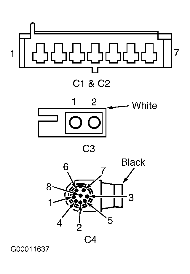 Courtesy of DAIMLERCHRYSLER CORP.