Mirror Control Switch Circuit Test
- Turn ignition off. Disconnect mirror switch harness connector. Using an ohmmeter, check continuity between mirror control switch harness connector terminal No. 1 (Black/White wire) and ground. See Fig 1
. If continuity does not exist, go to next step. If continuity exists, check Black/White wire between mirror control switch and mirror assemblies for short to ground.
- Check for continuity between harness connector terminal No. 2 (Green/Red wire) and terminal No. 3 (Red/Green wire). See Fig 1
. If continuity exists, go to next step. If continuity does not exist, illumination circuit is faulty. Repair as necessary.
- Turn ignition switch to ACC position. Using a voltmeter, check voltage between ground and terminal No. 4 (Red/Blue wire). See Fig 1
. If battery voltage exists, turn ignition off and go to next step. If battery voltage does not exist, check AUDIO (15-amp) fuse. If fuse is okay, check for an open in Red/Blue wire. Repair as necessary.
- Using an ohmmeter, connect negative lead to terminal No. 1 (Black/White wire) of mirror control switch harness connector. With ohmmeter positive lead, check for continuity at terminals No. 5, 7, 8 and 10. See Fig 1
. If continuity does not exist at all terminals, locate and repair open in Black/White wire. If continuity does not exist at only one terminal, check related circuit between connector and both mirror assemblies. See WIRING DIAGRAMS
. If circuit is okay, check for faulty mirror motor. Repair as necessary.
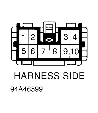 Courtesy of ISUZU MOTOR CO.