- Disconnect the battery cable from the negative terminal.
- Drain ATF through drain plug.
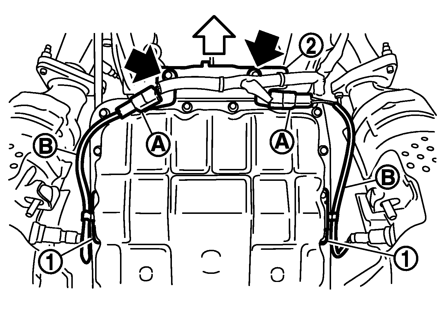
- Remove bracket (2) from transmission assembly. (for VQ35DE models)
 Courtesy of NISSAN MOTOR CO., U.S.A.
- Remove heated oxygen sensor 2 harness (B) from clips (1).
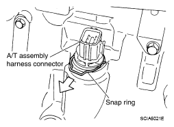
- Remove snap ring from A/T assembly harness connector.
- Disconnect A/T assembly harness connector.
- Remove snap ring from A/T assembly harness connector.
 Courtesy of NISSAN MOTOR CO., U.S.A.
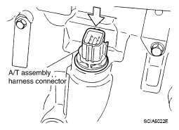
- Push A/T assembly harness connector.
CAUTION:
Be careful not to damage connector.
 Courtesy of NISSAN MOTOR CO., U.S.A.
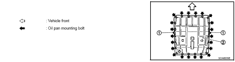
- Remove oil pan, oil pan gasket and clips (VQ35DE models) or oil pan, oil pan gasket, brackets and clips (VK45DE models) according to the following procedures.
- VQ35DE models
- Remove clips (1).
- Remove oil pan (2) and oil pan gasket.
 Courtesy of NISSAN MOTOR CO., U.S.A.
- VK45DE models
- Remove clips (1) and brackets (2).
- Remove oil pan (3) and oil pan gasket.
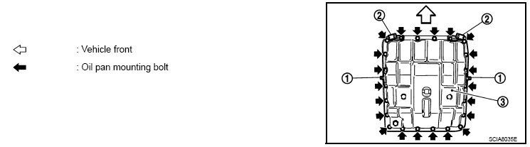 Courtesy of NISSAN MOTOR CO., U.S.A.
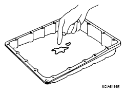
- Check foreign materials in oil pan to help determine causes of malfunction. If the ATF is very dark, smells burned, or contains foreign particles, the frictional material (clutches, band) may need replacement. A tacky film that will not wipe clean indicates varnish build up. Varnish can cause valves, servo, and clutches to stick and can inhibit pump pressure.
- If frictional material is detected, perform A/T fluid cooler cleaning.
Refer to
"A/T FLUID COOLER CLEANING ".
 Courtesy of NISSAN MOTOR CO., U.S.A.
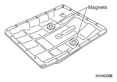
- Remove magnets from oil pan.
 Courtesy of NISSAN MOTOR CO., U.S.A.
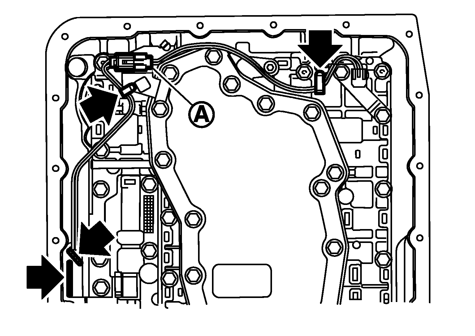
- Disconnect A/T fluid temperature sensor 2 connector.
CAUTION:
Be careful not to damage connector.
- Straighten terminal clips (←) to free terminal cord assembly A/T fluid temperature sensor 2 harness.
 Courtesy of NISSAN MOTOR CO., U.S.A.
- Disconnect revolution sensor connector.
CAUTION:
Be careful not to damage connector.
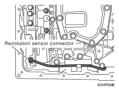 Courtesy of NISSAN MOTOR CO., U.S.A.
- Straighten terminal clip to free revolution sensor harness.
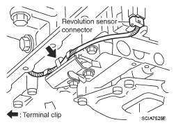 Courtesy of NISSAN MOTOR CO., U.S.A.
- Remove bolts A, B and C from control valve with TCM.
BOLTS SPECIFICATIONS
| Bolt symbol |
Length mm (in) |
Number of bolts |
| A |
42 (1.65) |
5 |
| B |
55 (2.17) |
6 |
| C |
40 (1.57) |
1 |
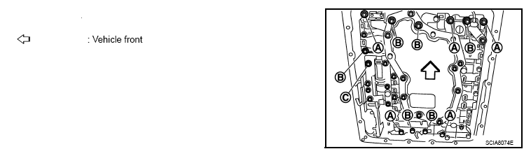 Courtesy of NISSAN MOTOR CO., U.S.A.
- Remove control valve with TCM from transmission case.
CAUTION:
When removing, be careful with the manual valve notch and manual plate height. Remove it vertically.
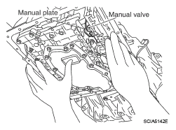 Courtesy of NISSAN MOTOR CO., U.S.A.
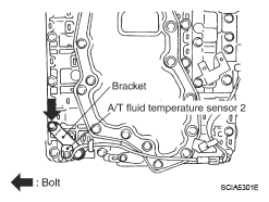
- Remove A/T fluid temperature sensor 2 with bracket from control valve with TCM.
 Courtesy of NISSAN MOTOR CO., U.S.A.
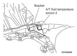
- Remove bracket from A/T fluid temperature sensor 2.
 Courtesy of NISSAN MOTOR CO., U.S.A.
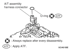
- Remove O-ring from A/T assembly harness connector.
 Courtesy of NISSAN MOTOR CO., U.S.A.
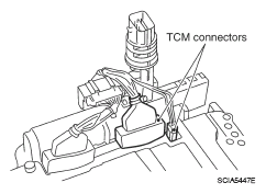
- Disconnect TCM connectors.
CAUTION:
Be careful not to damage connectors.
 Courtesy of NISSAN MOTOR CO., U.S.A.
- Remove A/T assembly harness connector from control valve with TCM using flat-blade screwdriver.
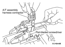 Courtesy of NISSAN MOTOR CO., U.S.A.
- Disconnect TCM connector and park/neutral position switch connector
CAUTION:
Be careful not to damage connectors.
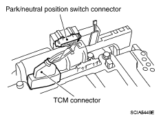 Courtesy of NISSAN MOTOR CO., U.S.A.