- Disconnect the battery cable from the negative terminal.
- Drain ATF through drain plug.
- Remove exhaust mounting bracket. Refer to
"EXPLODED VIEW
".
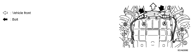
- Disconnect heated oxygen sensor 2 harness connectors (A).
 Courtesy of NISSAN MOTOR CO., U.S.A.
- Remove heated oxygen sensor 2 harness (B) from clips (1).
- Remove bracket (2) from transmission assembly.
- Disconnect A/T assembly harness connector.
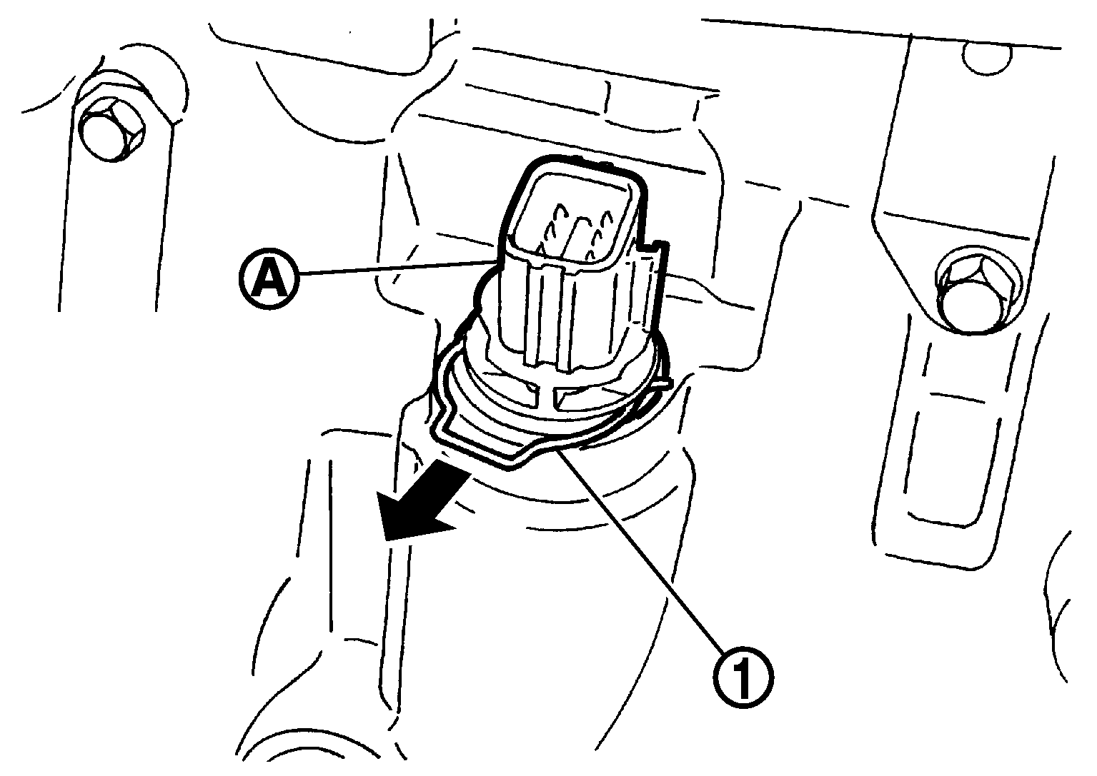
- Remove snap ring (1) from A/T assembly harness connector (A).
 Courtesy of NISSAN MOTOR CO., U.S.A.
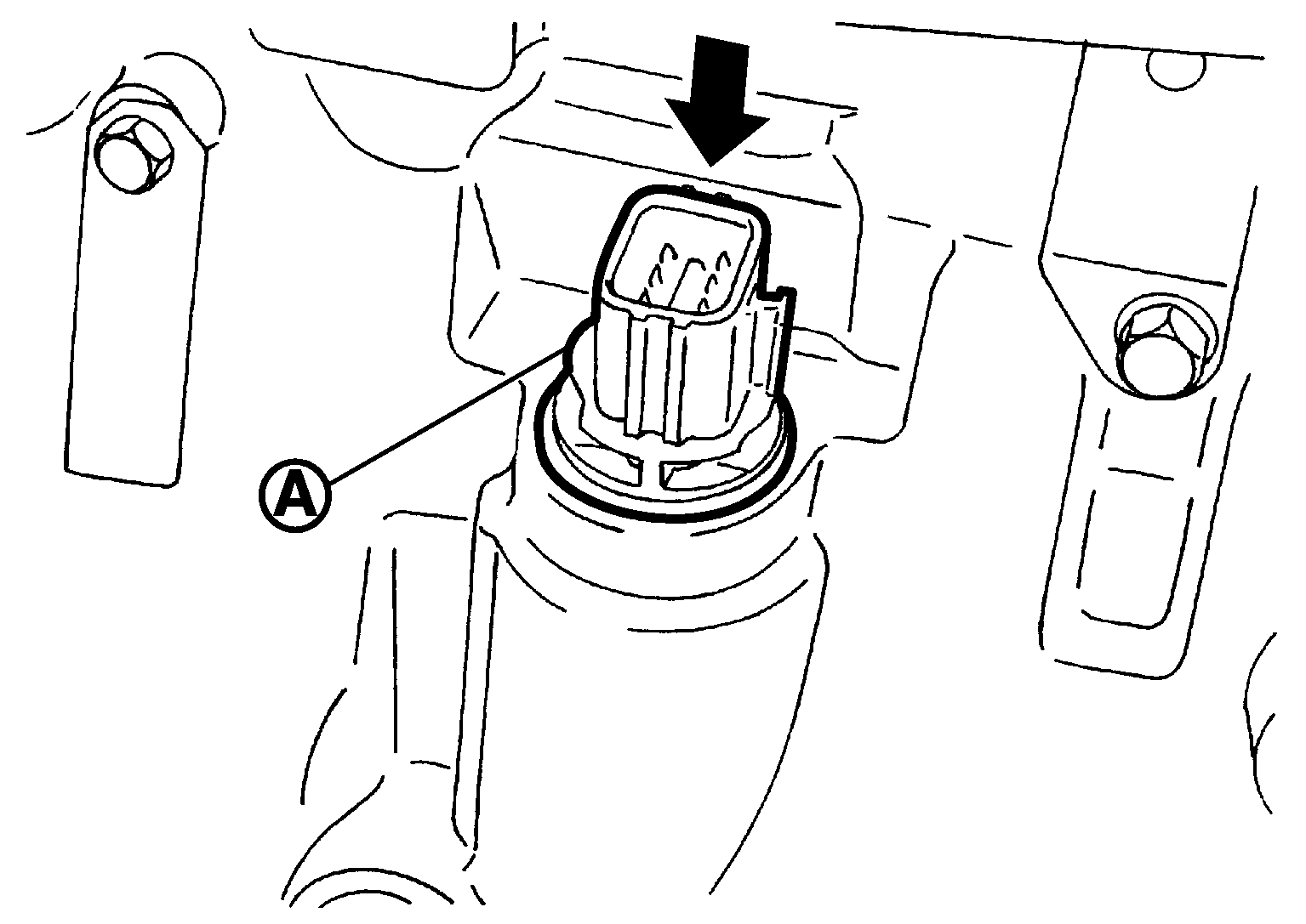
- Push A/T assembly harness connector (A).
CAUTION:
Be careful not to damage connector.
 Courtesy of NISSAN MOTOR CO., U.S.A.
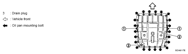
- Remove clips (1).
- Remove oil pan (2) and oil pan gasket.
 Courtesy of NISSAN MOTOR CO., U.S.A.
- Remove magnets (1) from oil pan.
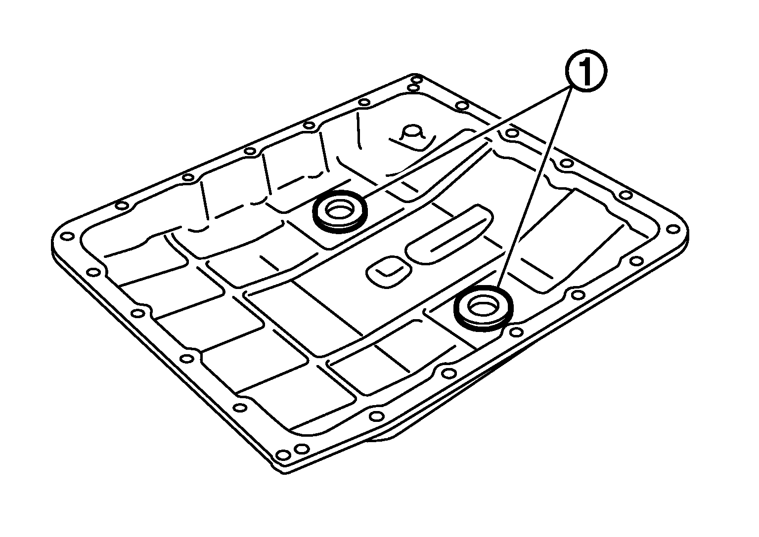 Courtesy of NISSAN MOTOR CO., U.S.A.
- Disconnect A/T fluid temperature sensor 2 connector (A).
CAUTION:
Be careful not to damage connector.
- Disengage terminal clips (<=).
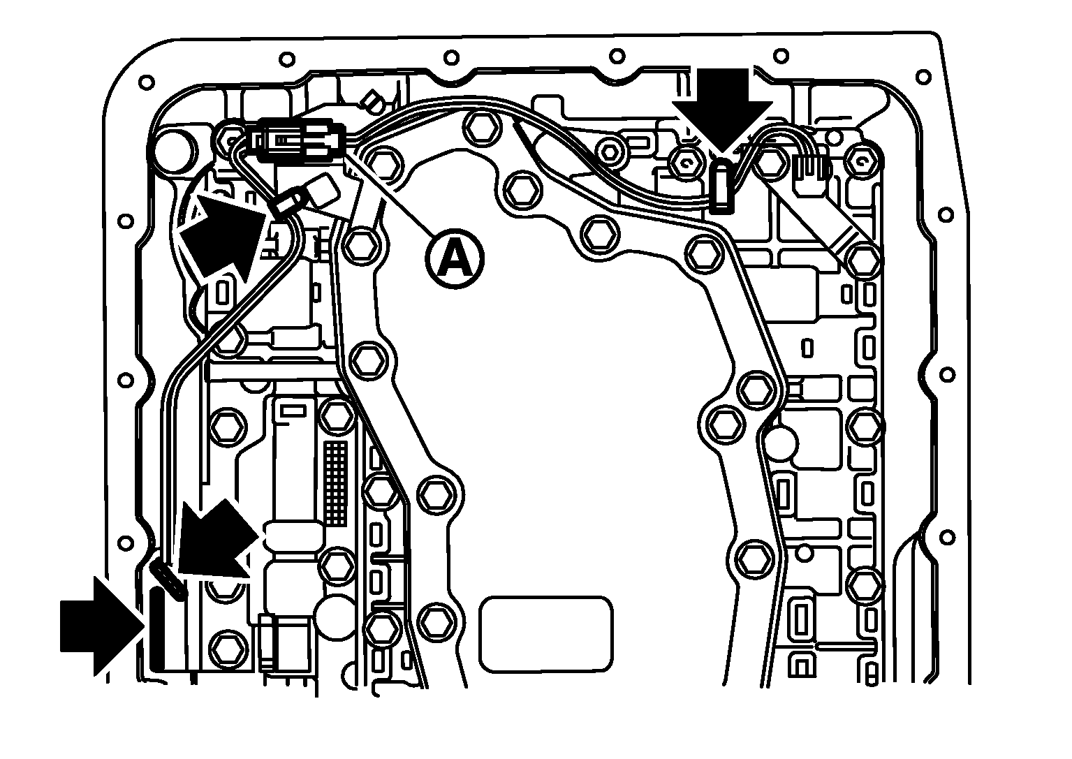 Courtesy of NISSAN MOTOR CO., U.S.A.
- Disconnect revolution sensor connector (A).
CAUTION:
Be careful not to damage connector.
- Disengage terminal clip (<=).
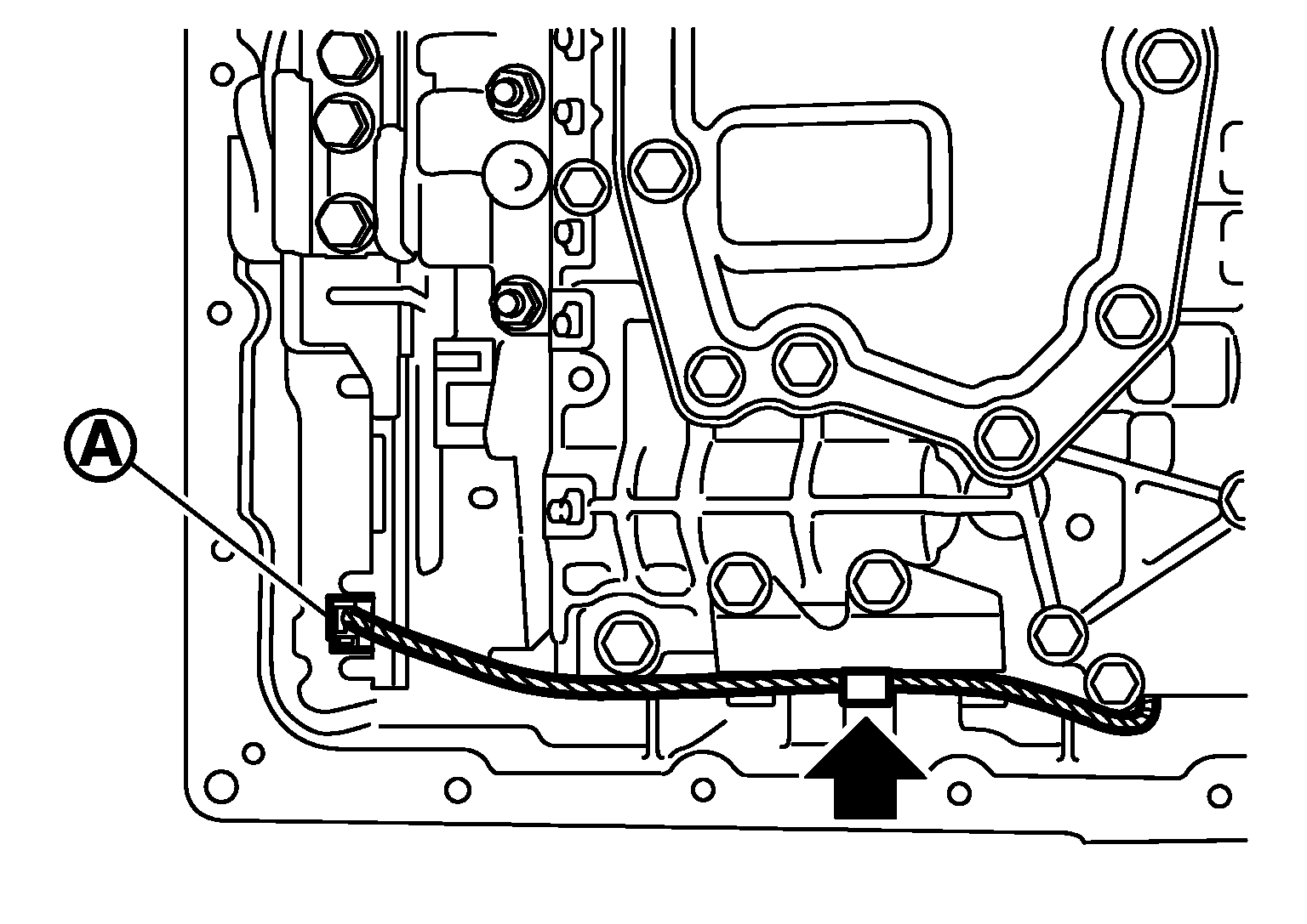 Courtesy of NISSAN MOTOR CO., U.S.A.
- Remove bolts (A), (B) and (C) from control valve with TCM.
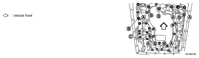 Courtesy of NISSAN MOTOR CO., U.S.A.
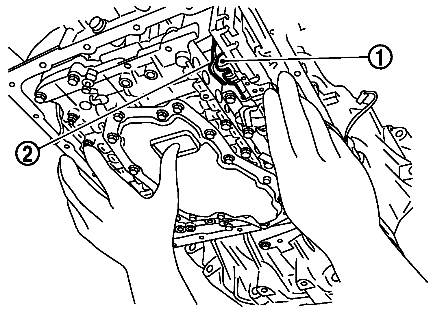
- Remove control valve with TCM from transmission case.
CAUTION:
When removing, be careful with the manual valve (1) notch and manual plate (2) height. Remove it vertically.
 Courtesy of NISSAN MOTOR CO., U.S.A.
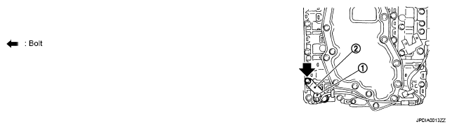
- Remove A/T fluid temperature sensor 2 (1) with bracket (2) from control valve with TCM.
 Courtesy of NISSAN MOTOR CO., U.S.A.
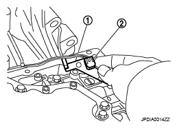
- Remove bracket (1) from A/T fluid temperature sensor 2 (2).
 Courtesy of NISSAN MOTOR CO., U.S.A.
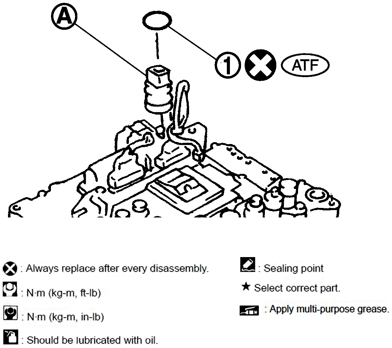
- Remove O-ring (1) from A/T assembly harness connector (A).
 Courtesy of NISSAN MOTOR CO., U.S.A.
- Disconnect TCM connectors (A) and (B).
CAUTION:
Be careful not to damage connectors.
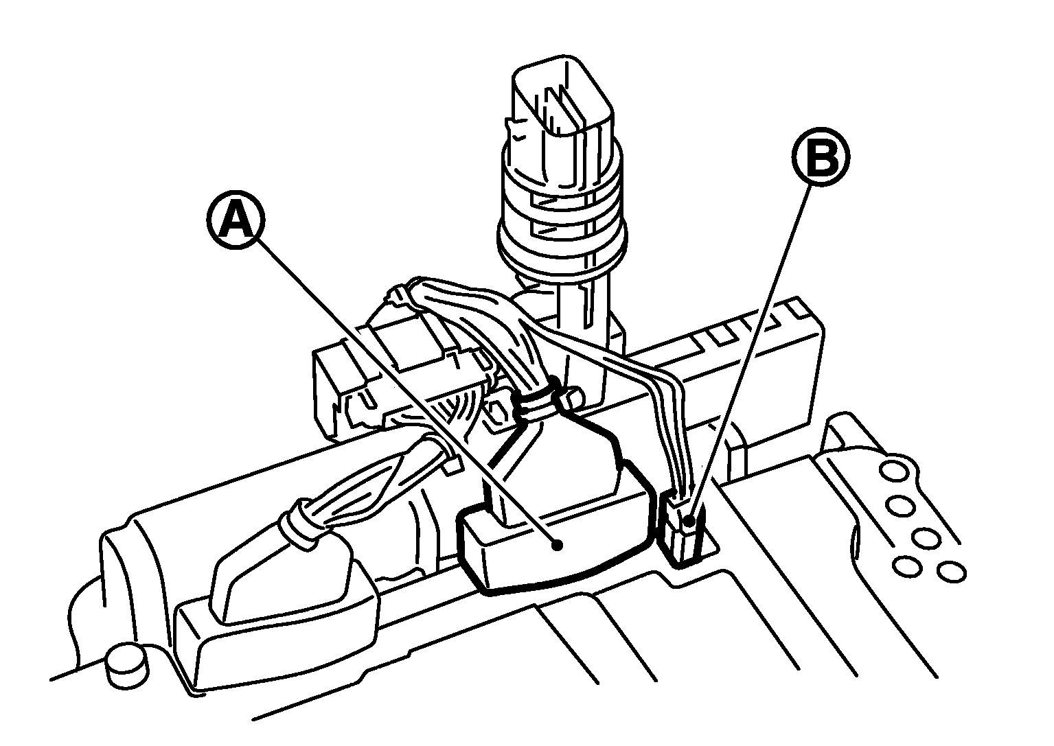 Courtesy of NISSAN MOTOR CO., U.S.A.
- Remove A/T assembly harness connector (A) from control valve with TCM using flat-blade screwdriver (B).
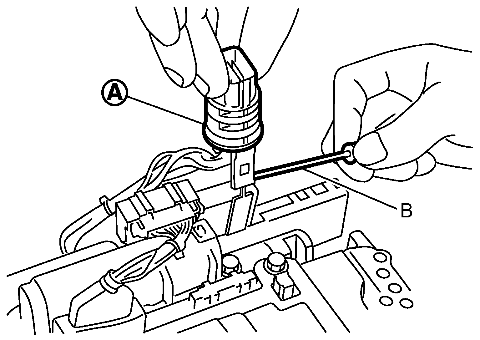 Courtesy of NISSAN MOTOR CO., U.S.A.
- Disconnect TCM connector (A) and park/neutral position switch connector (B).
CAUTION:
Be careful not to damage connectors.
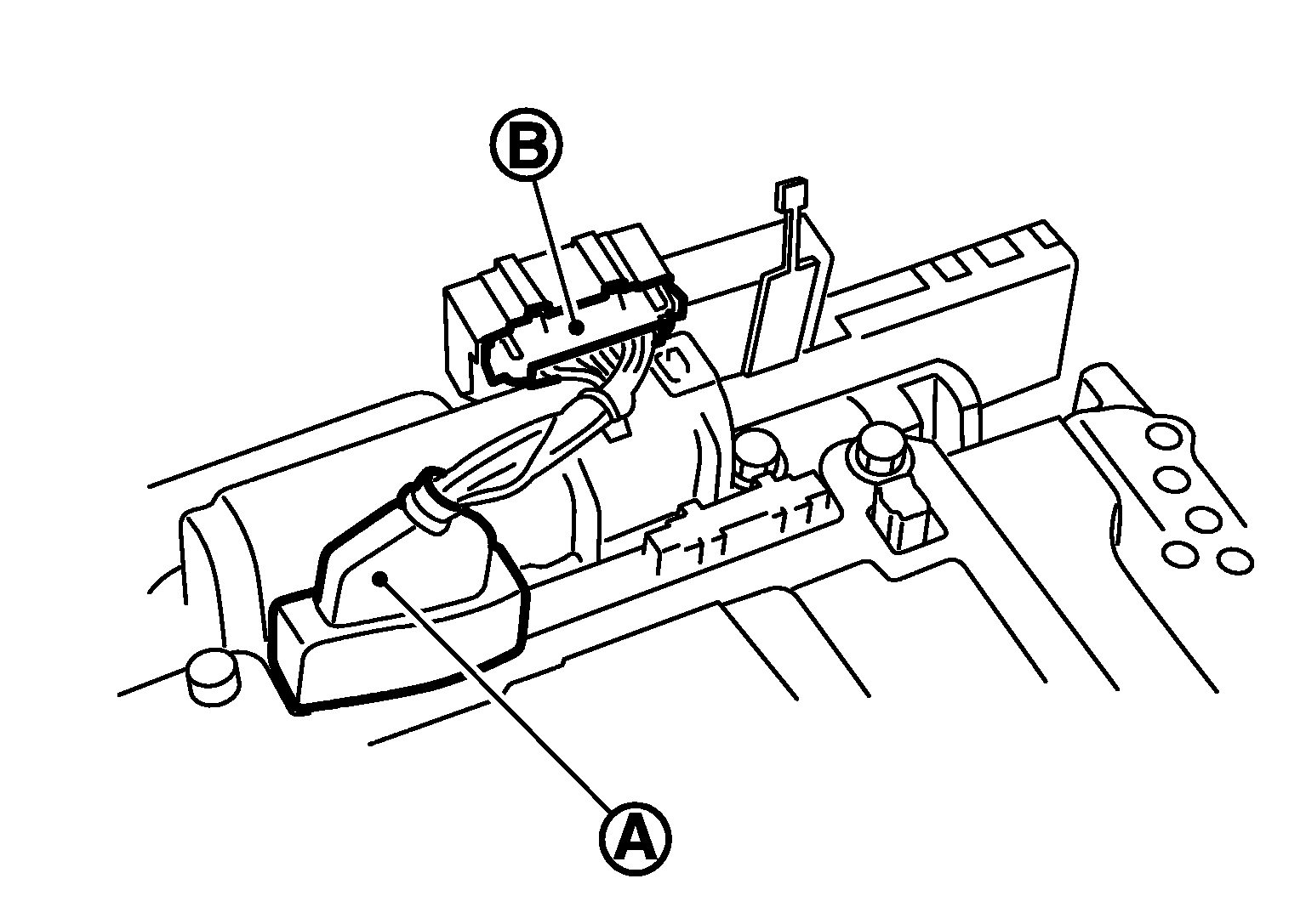 Courtesy of NISSAN MOTOR CO., U.S.A.