Test 5: ASCD Pump Circuit Check
- Turn ignition switch to LOCK position. Disconnect ASCD pump harness connector. Measure resistance between specified ASCD pump connector terminals. See ASCD PUMP RESISTANCE
table. See Fig 1
. If resistance is as specified, go to next step. If resistance is not as specified, replace ASCD pump.
ASCD PUMP RESISTANCE
| Measure Resistance Between Terminals No. |
Approximate Ohms |
| 1 & 2 |
65 |
| 1 & 3 |
65 |
| 1 & 4 |
3 |
- Ensure ignition switch is in LOCK position. Ensure ASCD pump is still disconnected. Disconnect ASCD control unit harness connector. Check each circuit for an open or short between ASCD pump and ASCD control unit harness connectors. Repair as necessary. See WIRING DIAGRAMS
.
- Turn ignition switch to LOCK position. Raise and support vehicle. Connect ASCD control unit harness connector. Turn ignition on and start engine. With gear selector in "D" position, slowly accelerate to 25 MPH. Ensure MAIN switch is in ON position. Press SET switch. Using an analog voltmeter, backprobe ASCD control unit harness connector. Measure voltage between ground and ASCD control unit harness connector terminal No. 12 (White/Blue wire). See Figure
. If battery voltage is present, power supply circuit is okay. If battery voltage is not present, replace ASCD control unit.
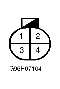 Courtesy of NISSAN MOTOR CO., U.S.A.