Camshaft Position Sensor Hall Effect (MFI Calif. & New York)
- A malfunction in the camshaft position sensor circuit will set diagnostic trouble Code 42. For testing procedures, see TESTS W/CODES
article in this section. Use the following procedure to diagnose camshaft position sensor.
- Turn ignition off. Remove distributor cap. Remove rotor and signal rotor cover from distributor housing. Using voltmeter, probe Yellow ECM 26-pin electrical connector C2 terminal No. 3 to ground. ECM is located behind left side of dash. Turn ignition on.
- CMP sensor voltage with signal rotor inserted between Hall element and magnet (magnetic flux cut off) should be 3-5 volts. See Fig 1
. If voltage is as specified, go to next step. If voltage is not as specified, check for faulty wiring and ECM. If wiring and ECM are okay, replace distributor housing.
- CMP sensor voltage without signal rotor inserted between Hall element and magnet (magnetic flux applied) should be 0-1 volt. See Fig 1
. If voltage is as specified, CMP sensor is okay. Turn ignition off and reverse disassembly procedure.
- If voltage is not as specified, check for faulty wiring and ECM. If wiring and ECM are okay, replace distributor housing. When testing is complete, reverse disassembly procedure.
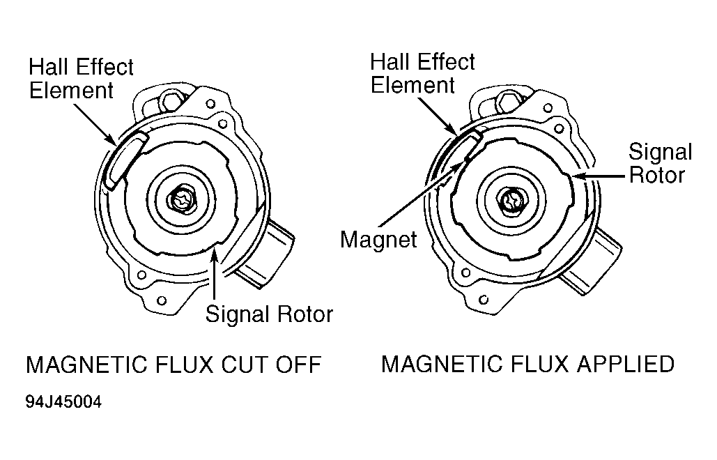 Courtesy of GENERAL MOTORS CORP.