Idle Speed
- Place transaxle in Park (A/T) or Neutral (M/T) and apply parking brake. Ensure throttle cable has at least .4-.6" (10.-15. mm) of slack in cable. Adjust throttle cable slack (if necessary).
- Ensure all emission hoses, electrical connections and air cleaner are properly installed. Ensure ignition timing is within specification. See IGNITION TIMING
. Ensure all accessories are off. Remove cover from idle speed adjusting screw.
- Start engine and warm to normal operating temperature. Accelerate engine so engine speed exceeds 1500 RPM, then allow to idle. Connect scan tester to duty check Data Link Connector (DLC). On TBI (Federal), connect a jumper wire between duty check DLC terminals "B" (Blue/Yellow wire), located near fusible link box by the battery, and ground. See Figure
and Figure
.
- On MFI (Calif. and New York), connect a jumper wire between duty check DLC terminals No. 2 (Blue/Yellow wire) and No. 4 (Black wire), located near the fusible link box by the battery. See Figure
. On all models, idle speed should be within specification. See IDLE SPEED SPECIFICATIONS
.
- If idle speed requires adjustment, turn idle speed adjusting screw to obtain correct idle speed. See Fig 1
and Fig 2
.
- On A/C-equipped models, turn A/C to low speed. With the A/C operating, idle speed should be within specification. Refer to A/C IDLE SPEED SPECIFICATIONS
.
- If idle speed requires adjustment, turn idle speed adjusting screw to obtain correct idle speed. See Fig 1
and Fig 2
.
- On all models, turn engine off. Remove jumper wire from duty check DLC. Install idle speed adjusting screw cover (if removed), and remove scan tester.
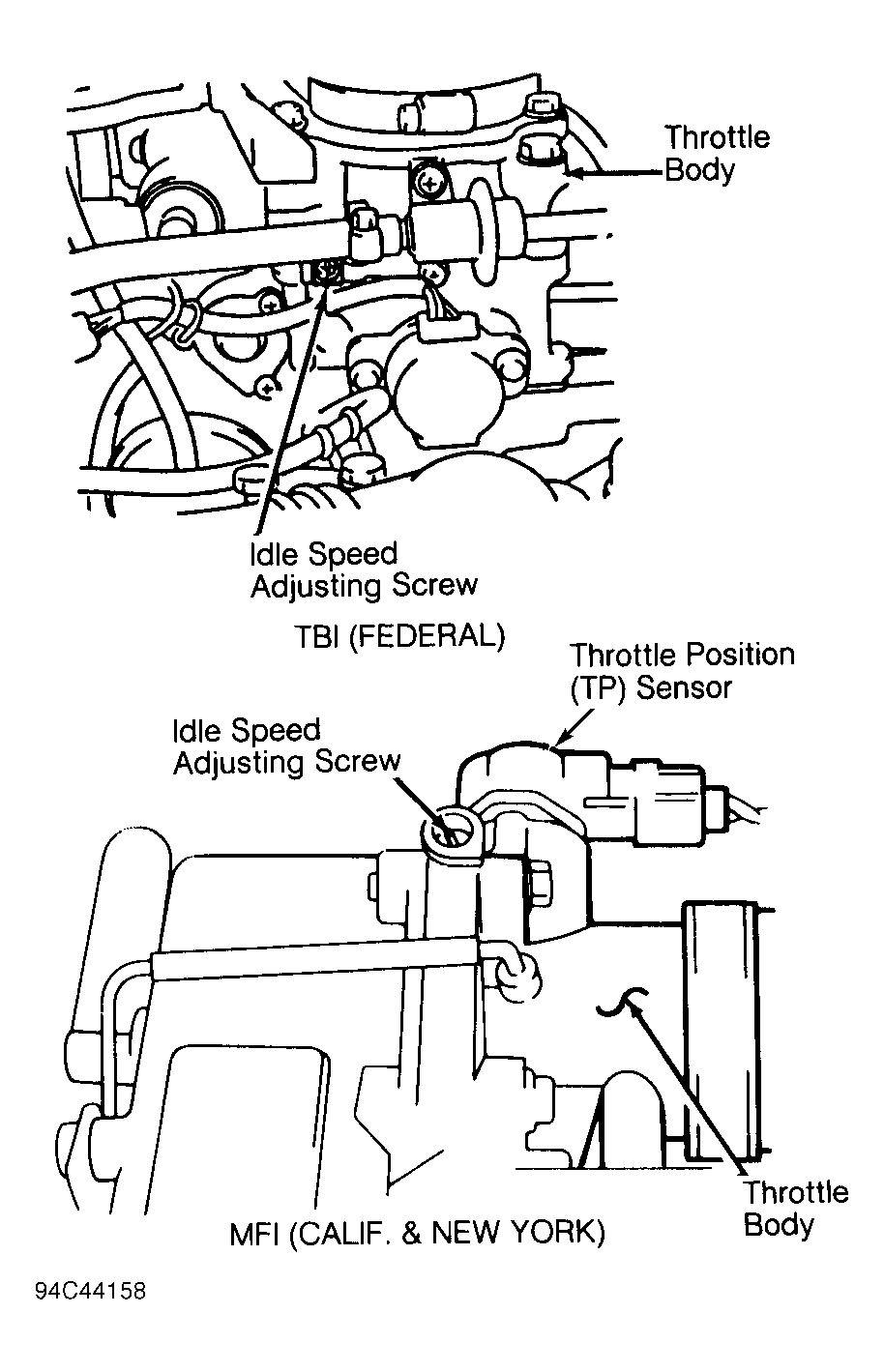 Courtesy of GENERAL MOTORS CORP.
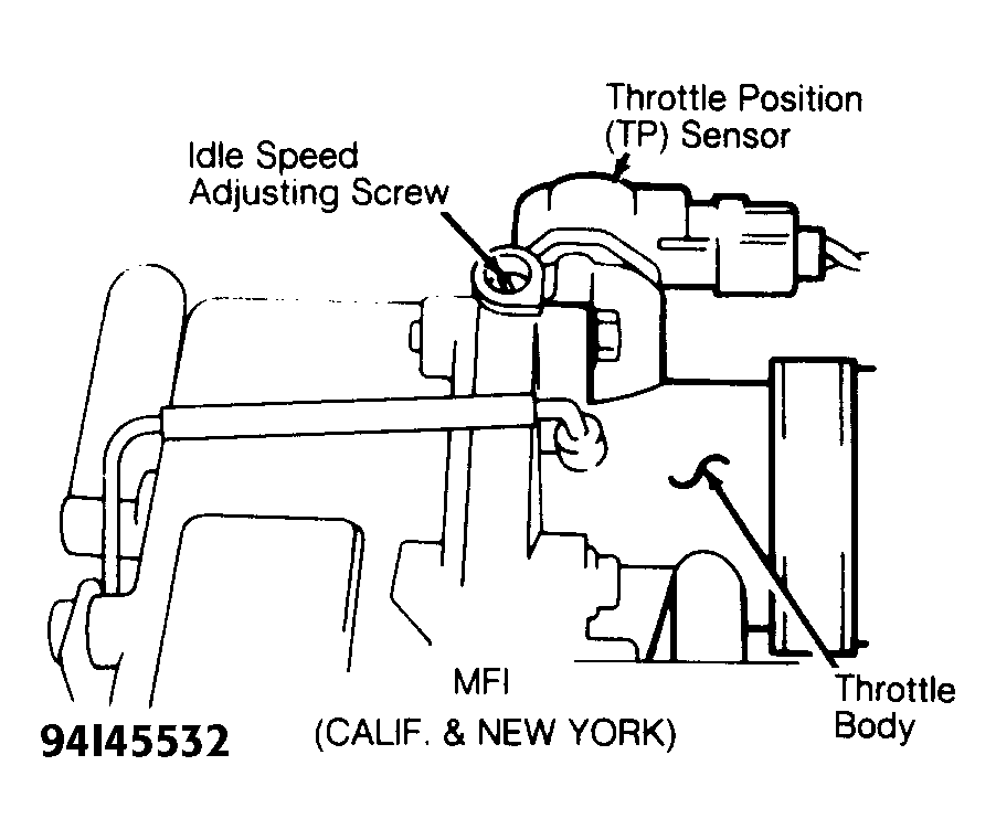 Courtesy of GENERAL MOTORS CORP.
 IDLE SPEED SPECIFICATIONS
| Application |
RPM |
| Tracker |
(5) 750-850 |
A/C IDLE SPEED SPECIFICATIONS
| Application |
RPM |
| A/T |
|
| M/T |
950-1050 |