Pinpoint Test V: The Panel/Floor Control Does Not Operate Using The Front/Rear Auxiliary Climate Controls
- V1 CHECK THE FRONT AUXILIARY MODE CONTROL OPERATION
- Key in ON position.
- Place the front auxiliary blower motor switch in the HI position.
- Rotate the front auxiliary mode control switch from PANEL to FLOOR.
- Does the front mode control operate correctly?
- Yes
: GO to V2.
- No
: GO to V8.
- V2 TEST THE REAR AUXILIARY MODE CONTROL OPERATION
- Place the front auxiliary blower motor switch in the REAR position.
- Place the rear auxiliary blower motor switch in the HI position.
- Rotate the rear auxiliary mode control switch from PANEL to FLOOR.
- Does the rear mode control operate correctly?
- Yes
: System is OK.
- No
: GO to V3.
- V3 CHECK CIRCUIT 1130 (PK/LG)
- Key in OFF position.
- Disconnect: Rear Auxiliary Mode Control Switch C990c.
- Disconnect: Auxiliary Climate Control Module C3005.
- Measure the resistance between rear auxiliary mode control switch C990c pin 2, circuit 1130 (PK/LG) and auxiliary climate control module C3005 pin 1, circuit 1130 (PK/LG); and between auxiliary climate control module C3005 pin 1, circuit 1130 (PK/LG) and ground.
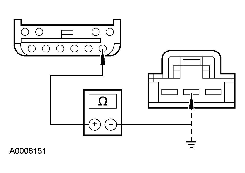 Courtesy of FORD MOTOR CO.
- Is the resistance less than 5 ohms between the rear auxiliary mode control switch and the auxiliary climate control module, and greater than 10,000 ohms between the auxiliary climate control module and ground?
- Yes
: GO to V4.
- No
: REPAIR circuit 1130 (PK/LG). TEST the system for normal operation.
- V4 CHECK THE REAR AUXILIARY MODE CONTROL CIRCUIT 1129 (BN/WH)
- Disconnect: Auxiliary Mode Door Actuator C3044.
- Measure the resistance between rear auxiliary mode control switch C990c pin 3, circuit 1129 (BN/WH) and auxiliary mode door actuator C3044 pin 6, circuit 1129 (BN/WH).
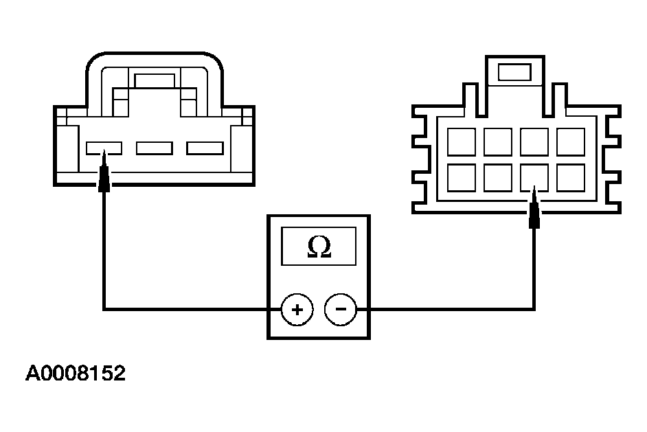 Courtesy of FORD MOTOR CO.
- Is the resistance less than 5 ohms?
- Yes
: GO to V5.
- No
: REPAIR circuit 1129 (BN/WH). TEST the system for normal operation.
- V5 CHECK THE REAR AUXILIARY MODE CONTROL CIRCUIT 1128 (GY/LB)
- Measure the resistance between rear auxiliary mode control switch C990c pin 1, circuit 1128 (GY/LB) and auxiliary mode door actuator C3044 pin 4, circuit 1128 (GY/LB).
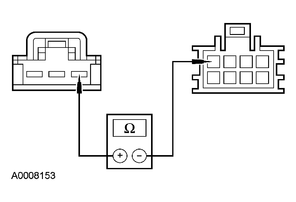 Courtesy of FORD MOTOR CO.
- Is the resistance less than 5 ohms?
- Yes
: GO to V6.
- No
: REPAIR circuit 1128 (GY/LB). TEST the system for normal operation.
- V6 CHECK THE REAR AUXILIARY MODE CONTROL SWITCH
- Measure the resistance between rear auxiliary mode control switch C990c pin 1 and pin 3, component side.
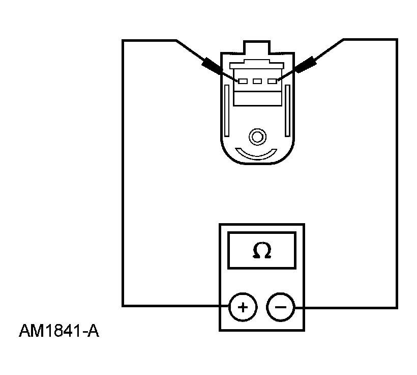 Courtesy of FORD MOTOR CO.
- Is the resistance between 4,000 and 6,000 ohms?
- Yes
: GO to V7.
- No
: INSTALL a new rear auxiliary mode control switch. TEST the system for normal operation
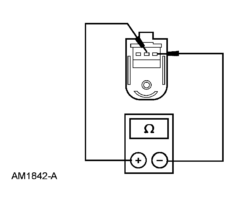
- V7 CHECK THE REAR AUXILIARY MODE CONTROL SWITCH WIPER
- Measure the resistance between rear auxiliary mode control switch pin 1 and pin 2, component side, while rotating the rear auxiliary mode control switch.
 Courtesy of FORD MOTOR CO.
- Does the resistance vary?
- Yes
: INSTALL a new auxiliary climate control module. TEST the system for normal operation.
- No
: INSTALL a new rear auxiliary mode control switch. refer to AUXILIARY CLIMATE CONTROL
. TEST the system for normal operation.
- V8 CHECK THE REAR AUXILIARY MODE CONTROL OPERATION
- Place the front auxiliary blower motor switch in the REAR position.
- Place the rear auxiliary blower motor switch in the HI position.
- Rotate the rear auxiliary mode control switch from PANEL to FLOOR.
- Does the rear mode control operate correctly?
- Yes
: GO to V9.
- No
: GO to V14.
- V9 CHECK CIRCUIT 1123 (YE/WH)
- Key in OFF position.
- Disconnect: Front Auxiliary Mode Control Switch C989c.
- Disconnect: Auxiliary Climate Control Module C3005.
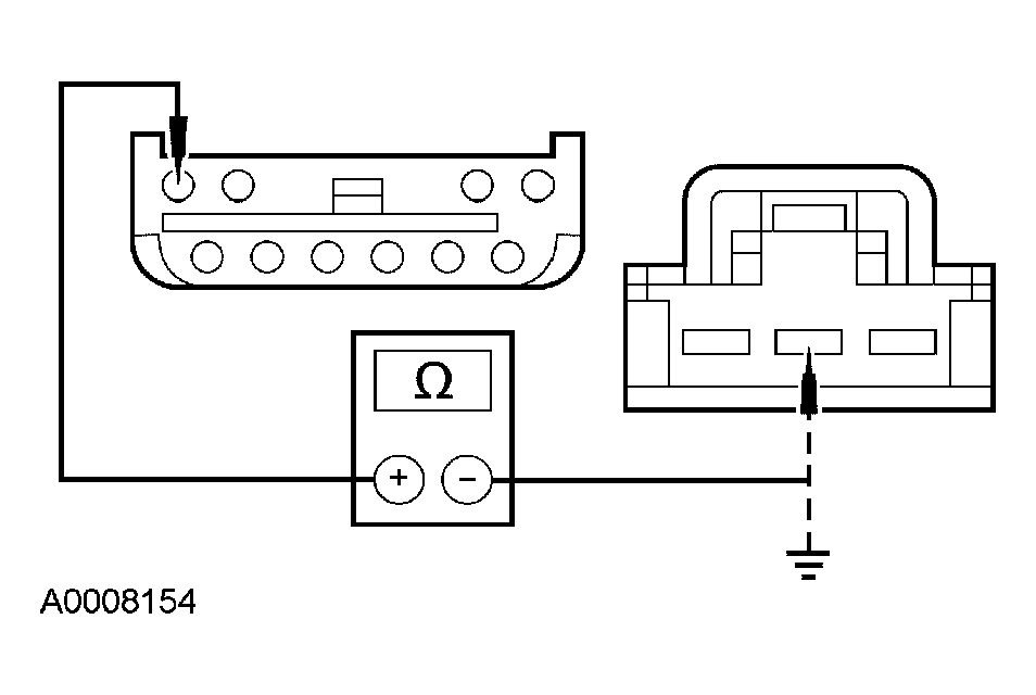
- Measure the resistance between front auxiliary mode control switch C989c pin 2, circuit 1123 (YE/WH) and auxiliary climate control module C3005 pin 10, circuit 1123 (YE/WH); and between auxiliary climate control module C3005 pin 10, circuit 1123 (YE/WH) and ground.
 Courtesy of FORD MOTOR CO.
- Is the resistance less than 5 ohms between the front auxiliary mode control switch and the auxiliary climate control module, and greater than 10,000 ohms between the auxiliary climate control module and ground?
- Yes
: GO to V10.
- No
: REPAIR circuit 1123 (YE/WH). TEST the system for normal operation.
- V10 CHECK THE FRONT AUXILIARY MODE CONTROL CIRCUIT 1129 (BN/WH)
- Disconnect: Auxiliary Mode Door Actuator C355.
- Measure the resistance between front auxiliary mode control switch C989c pin 3, circuit 1129 (BN/WH) and auxiliary mode door actuator C3044 pin 6, circuit 1129 (BN/WH).
Courtesy of FORD MOTOR CO.
- Is the resistance less than 5 ohms?
- Yes
: GO to V11.
- No
: REPAIR circuit 1129 (BN/WH). TEST the system for normal operation.
- V11 CHECK THE FRONT AUXILIARY MODE CONTROL CIRCUIT 1128(GY/LB)
- Measure the resistance between front auxiliary mode control switch C989c pin 1, circuit 1128 (GY/LB) and auxiliary mode door actuator C3044 pin 4, circuit 1128 (GY/LB).
Courtesy of FORD MOTOR CO.
- Is the resistance less than 5 ohms?
- Yes
: GO to V12.
- No
: REPAIR circuit 1128 (GY/LB). TEST the system for normal operation.
- V12 CHECK THE FRONT AUXILIARY MODE CONTROL SWITCH
- Measure the resistance between front auxiliary mode control switch pin 1 and pin 3, component side.
Courtesy of FORD MOTOR CO.
- Is the resistance between 4,000 and 6,000 ohms?
- Yes
: GO to V13.
- No
: INSTALL a new front auxiliary mode control switch. refer to AUXILIARY CLIMATE CONTROL
. TEST the system for normal operation.
- V13 CHECK THE FRONT AUXILIARY MODE CONTROL SWITCH WIPER
- Measure the resistance between front auxiliary mode control switch pin 1 and pin 2, component side.
Courtesy of FORD MOTOR CO.
- Does the resistance vary?
- Yes
: INSTALL a new auxiliary climate control module. TEST the system for normal operation.
- No
: INSTALL a new front auxiliary mode control switch. refer to AUXILIARY CLIMATE CONTROL
. TEST the system for normal operation.
- V14 CHECK THE VOLTAGE TO THE AUXILIARY MODE DOOR ACTUATOR
- Key in OFF position.
- Disconnect: Auxiliary Mode Door Actuator C3044.
- Key in ON position.
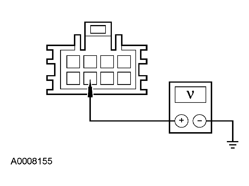
- Measure the voltage between auxiliary mode door actuator C3044 pin 7, circuit 295 (LB/PK) and ground.
 Courtesy of FORD MOTOR CO.
- Is the voltage greater than 10 volts?
- Yes
: GO to V15.
- No
: REPAIR circuit 295 (LB/PK). TEST the system for normal operation.
- V15 CHECK CIRCUIT 57 (BK)
- Key in OFF position.
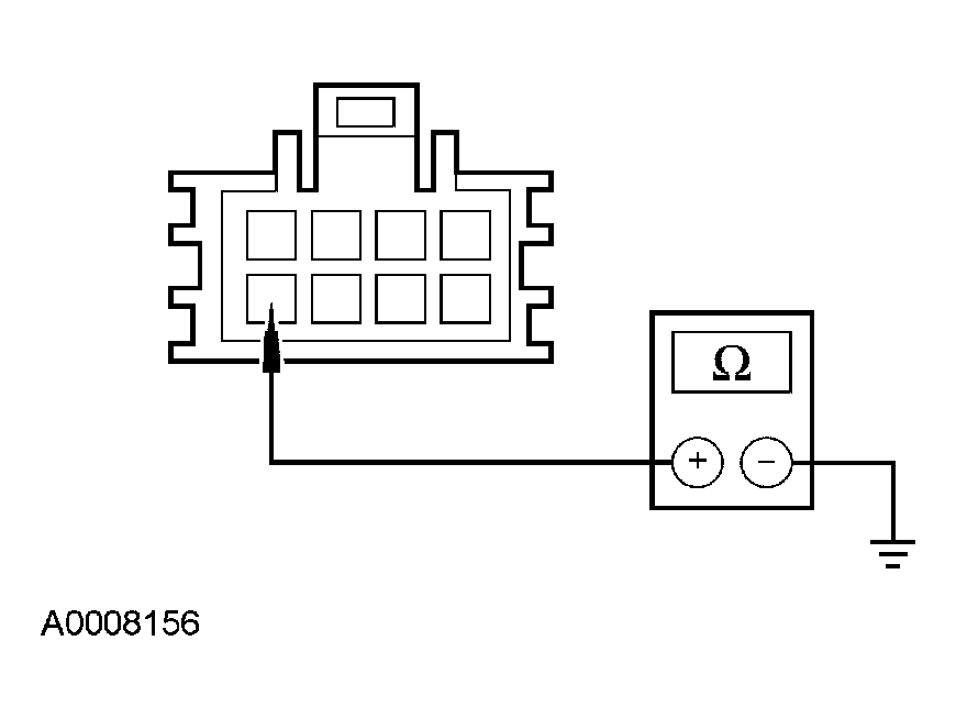
- Measure the resistance between auxiliary mode door actuator C3044 pin 8, circuit 57 (BK) and ground.
 Courtesy of FORD MOTOR CO.
- Is the resistance less than 5 ohms?
- Yes
: GO to V16.
- No
: REPAIR circuit 57 (BK). TEST the system for normal operation.
- V16 CHECK CIRCUIT 1131 (LG)
- Disconnect: Auxiliary Climate Control Module C353.
- Measure the resistance between auxiliary climate control module C3005 pin 3, circuit 1131 (LG) and auxiliary mode door actuator C3044 pin 3, circuit 1131 (LG); and between auxiliary mode door actuator C3044 pin 3, circuit 1131 (LG), and ground.
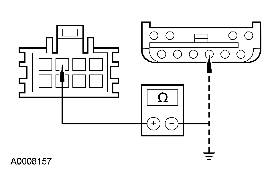 Courtesy of FORD MOTOR CO.
- Is the resistance less than 5 ohms between the auxiliary climate control module and the auxiliary mode door actuator, and greater than 10,000 ohms between the auxiliary mode door actuator and ground?
- Yes
: GO to V17.
- No
: REPAIR circuit 1131 (LG). TEST the system for normal operation.
- V17 CHECK CIRCUIT 1129 (BN/WH)
- Disconnect: Front Auxiliary Mode Control Switch C989c.
- Disconnect: Rear Auxiliary Mode Control Switch C990c.
- Measure the resistance between auxiliary mode door actuator C3044 pin 6, circuit 1129 (BN/WH) and rear auxiliary mode control switch C990c pin 3, circuit 1129 (BN/WH); and between auxiliary mode door actuator C3044 pin 6, circuit 1129 (BN/WH) and ground.
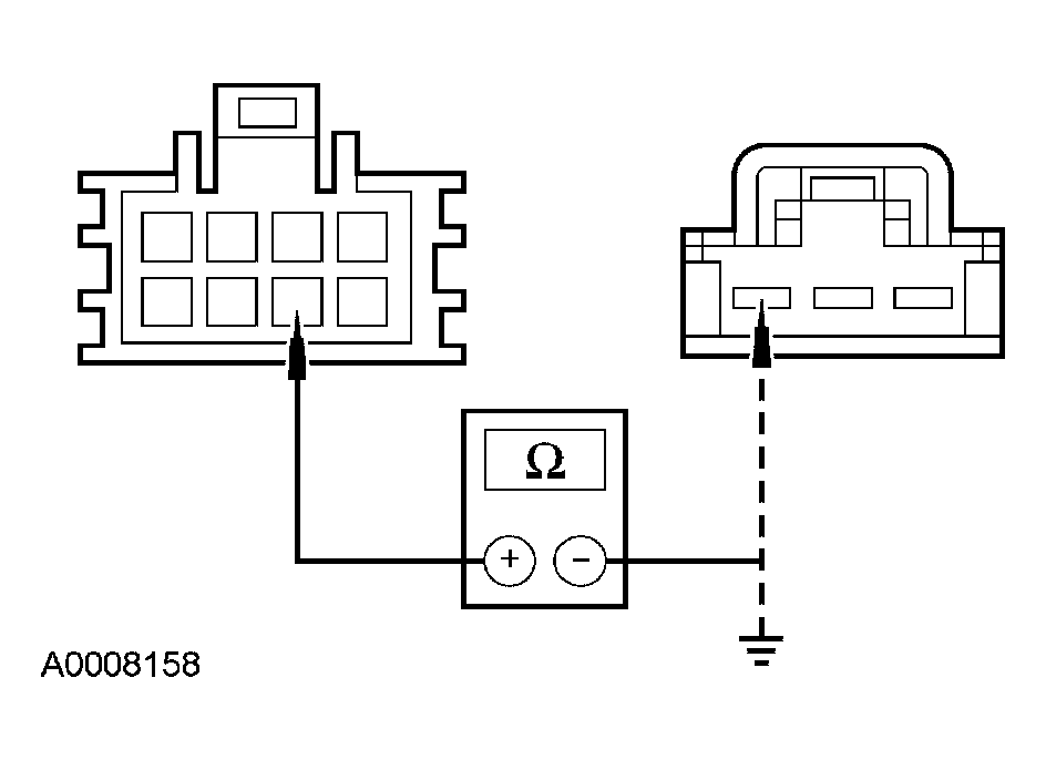 Courtesy of FORD MOTOR CO.
- Is the resistance less than 5 ohms between the auxiliary mode door actuator and the rear auxiliary mode control switch, and greater than 10,000 ohms between the auxiliary mode door actuator and ground?
- Yes
: GO to V18.
- No
: REPAIR circuit 1129 (BN/WH). TEST the system for normal operation.
- V18 CHECK CIRCUIT 1128 (GY/LB)
- Measure the resistance between auxiliary mode door actuator C3044 pin 4, circuit 1128 (GY/LB) and rear auxiliary mode control switch C990c pin 1, circuit 1128 (GY/LB); and between auxiliary mode door actuator C3044 pin 4, circuit 1128 (GY/LB) and ground.
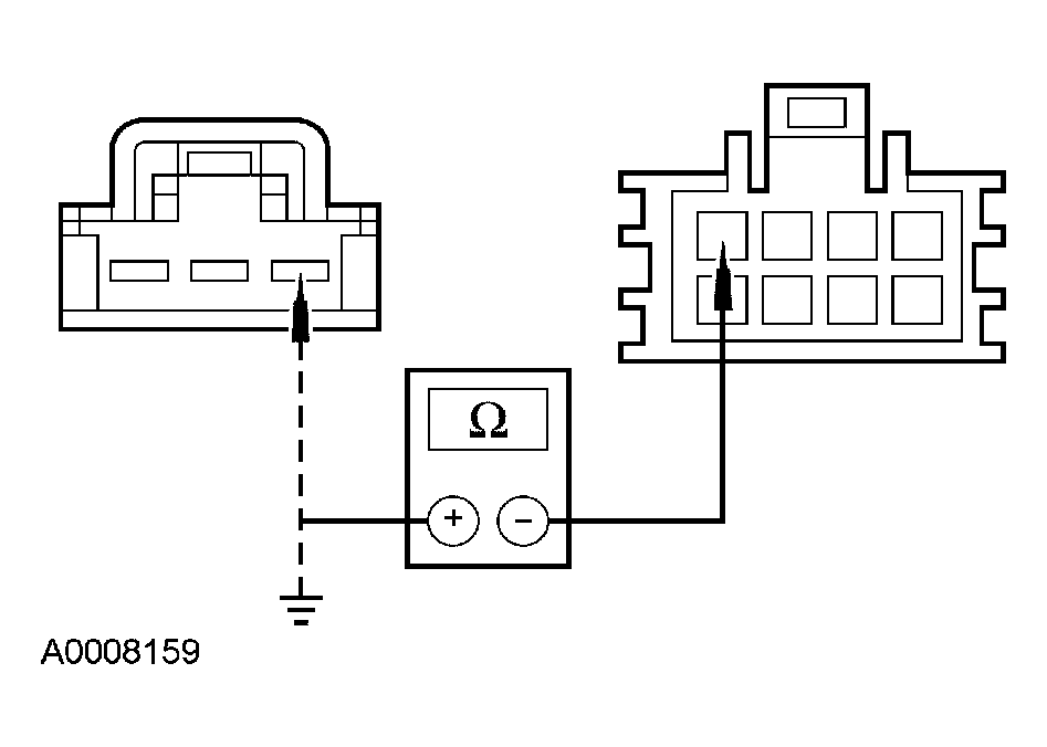 Courtesy of FORD MOTOR CO.
- Is the resistance less than 5 ohms between the auxiliary mode door actuator and the rear auxiliary mode control switch, and greater than 10,000 ohms between the auxiliary mode door actuator and ground?
- Yes
: GO to V19.
- No
: REPAIR circuit 1128 (GY/LB). TEST the system for normal operation.
- V19 CHECK CIRCUIT 1130 (PK/LG) FOR A SHORT
- Measure the resistance between auxiliary climate control module C3005 pin 1, circuit 1130 (PK/LG) and ground.
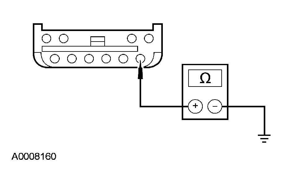 Courtesy of FORD MOTOR CO.
- Is the resistance greater than 10,000 ohms?
- Yes
: GO to V20.
- No
: REPAIR circuit 1130 (PK/LG). TEST the system for normal operation.
- V20 CHECK CIRCUIT 1123 (YE/WH) FOR A SHORT
- Measure the resistance between auxiliary climate control module C3005 pin 10, circuit 1123 (YE/WH) and ground.
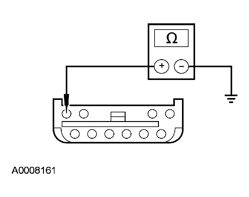 Courtesy of FORD MOTOR CO.
- Is the resistance greater than 10,000 ohms?
- Yes
: GO to V21.
- No
: REPAIR circuit 1123 (YE/WH). TEST the system for normal operation.
- V21 CHECK THE AUXILIARY MODE DOOR ACTUATOR - 12 VOLTS
- Connect: Auxiliary Mode Door Actuator C3044.
- Key in ON position.
- Place the front auxiliary blower motor switch in the HI position.
- Connect a fused jumper lead between auxiliary climate control module C3005 pin 8, circuit 295 (LB/PK) and pin 3, circuit 1131 (LG).
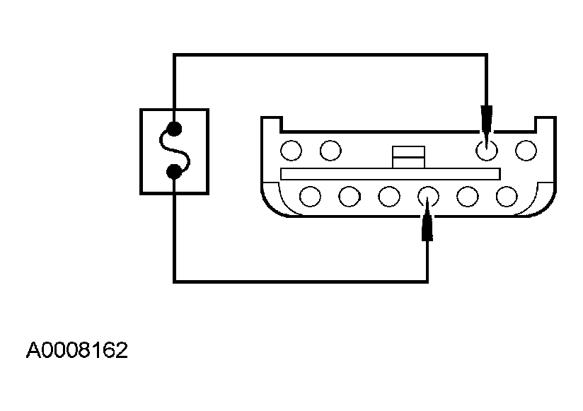 Courtesy of FORD MOTOR CO.
- Does the auxiliary mode door actuator direct airflow to the panel?
- Yes
: INSPECT for binding, stuck or broken blend door or linkage. If no condition is found, INSTALL a new auxiliary climate control module. TEST the system for normal operation.
- No
: GO to V22.
- V22 CHECK THE AUXILIARY MODE DOOR ACTUATOR - 0 VOLTS
- Connect a fused jumper lead between auxiliary climate control module C3005 pin 3, circuit 1131 (LG) and pin 6, circuit 57 (BK).
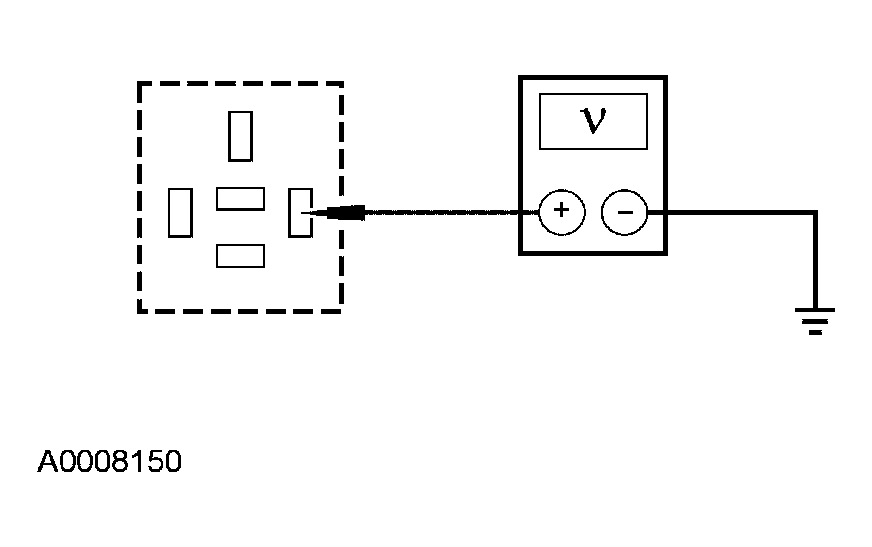 Courtesy of FORD MOTOR CO.
- Does the auxiliary mode door actuator direct airflow to the floor?
- Yes
: INSTALL a new auxiliary climate control module. TEST the system for normal operation.
- No
: INSPECT for a binding, stuck or broken auxiliary mode door or linkage. If no condition is found, INSTALL a new auxiliary mode door actuator. refer to AUXILIARY CLIMATE CONTROL
. TEST the system for normal operation.