Oil Pump - Early Build: Installation
- Install a new lower O-ring seal.
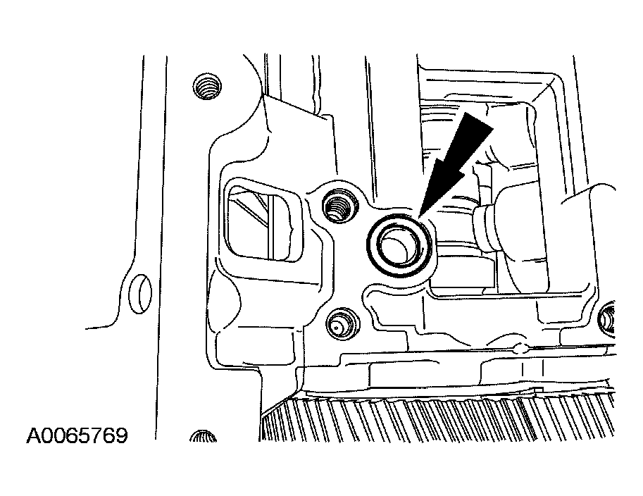 Courtesy of FORD MOTOR CO.
- Install the high-pressure oil pump and bolts.
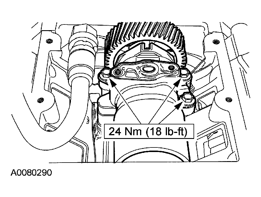 Courtesy of FORD MOTOR CO.
- Install the high-pressure pump O-ring seal.
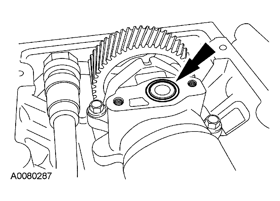 Courtesy of FORD MOTOR CO.
- Position back the high-pressure discharge tube and install the bolts.
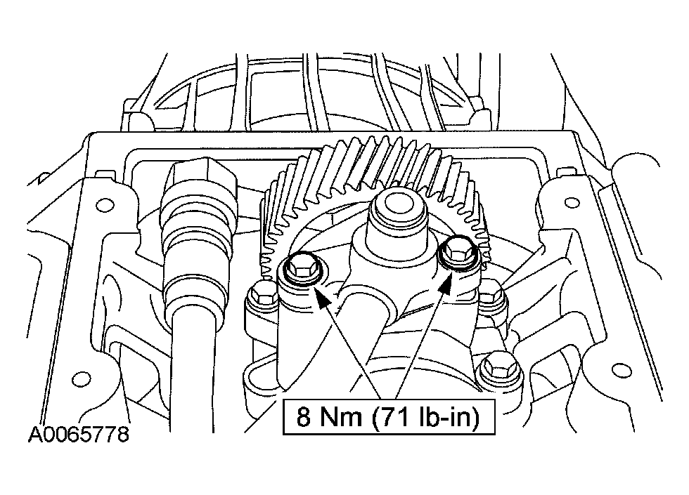 Courtesy of FORD MOTOR CO.
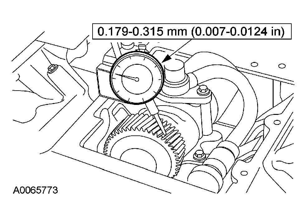
- Position the dial indicator with bracketry onto the oil pump drive and check the oil pump drive gear backlash.
 Courtesy of FORD MOTOR CO.
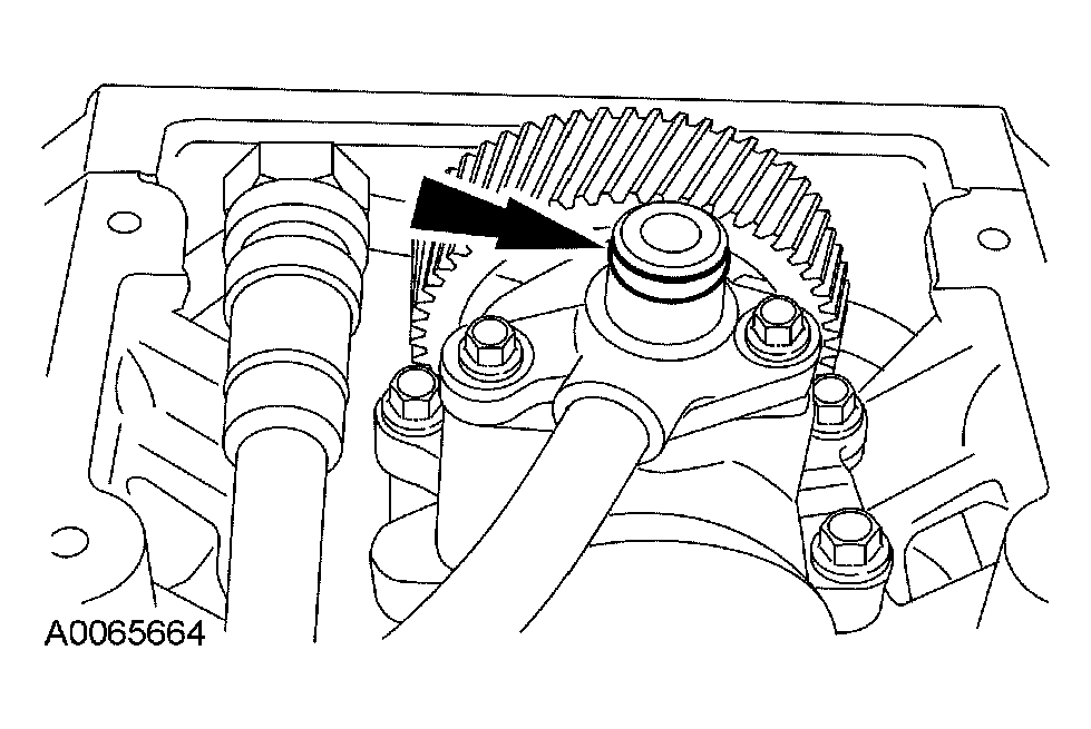
- Install a new O-ring seal on the high-pressure discharge pipe.
 Courtesy of FORD MOTOR CO.
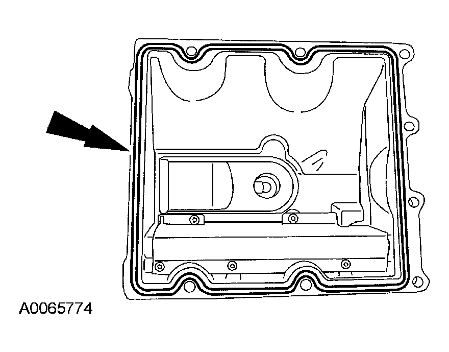
- Install a new press-in-place gasket in the high-pressure pump cover.
 Courtesy of FORD MOTOR CO.
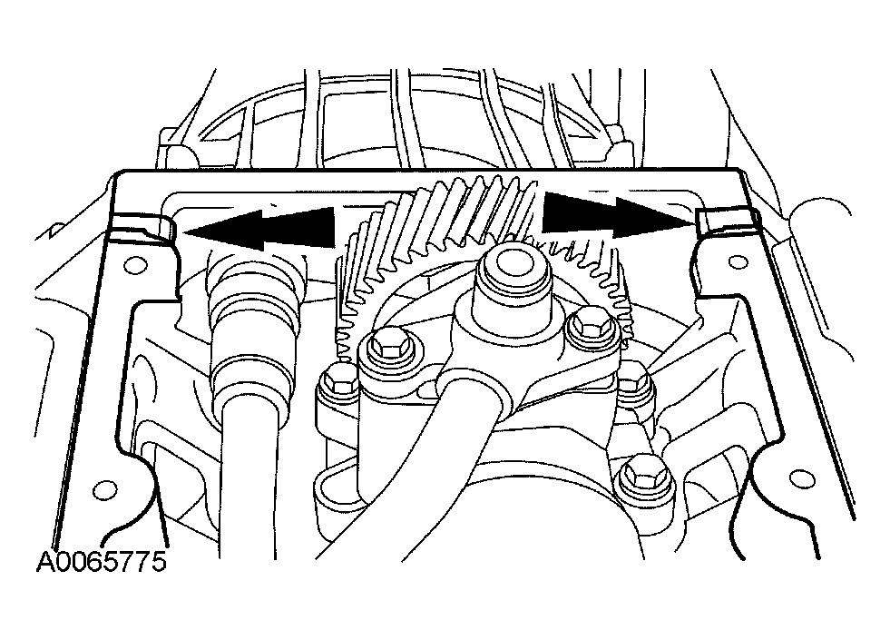
- Clean the cover mounting surface and apply sealer at the seams.
 Courtesy of FORD MOTOR CO.
- Install the high-pressure pump cover and bolts.
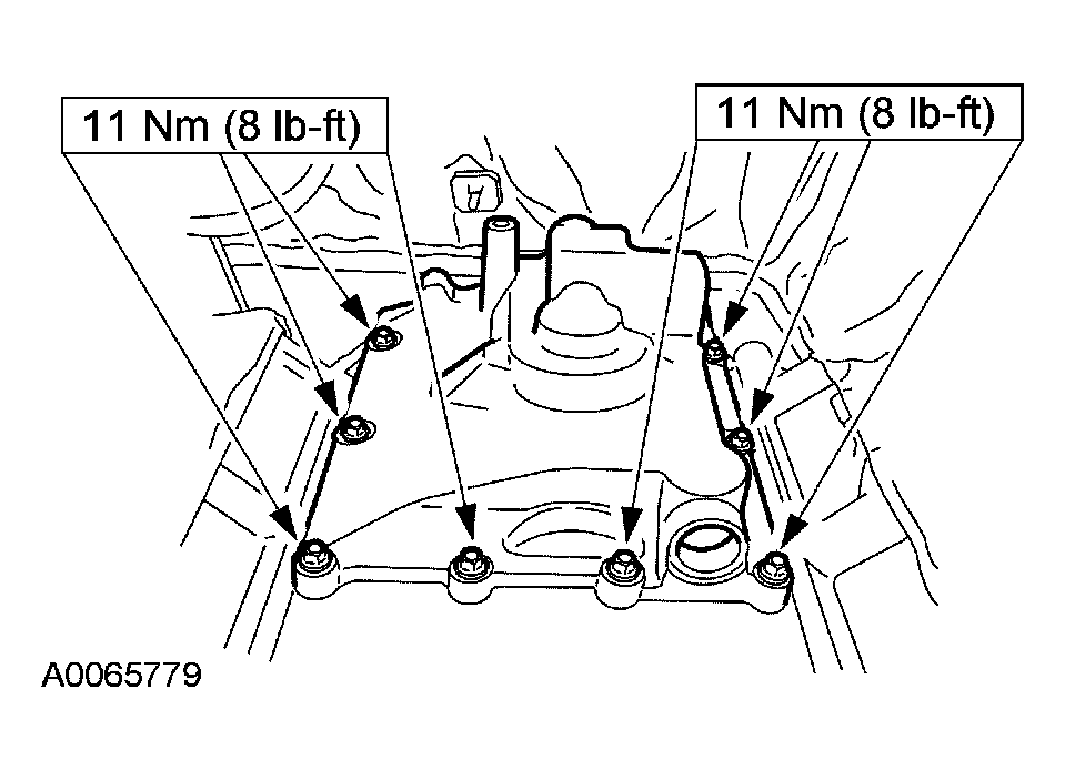 Courtesy of FORD MOTOR CO.
- Install the turbocharger heat shield.
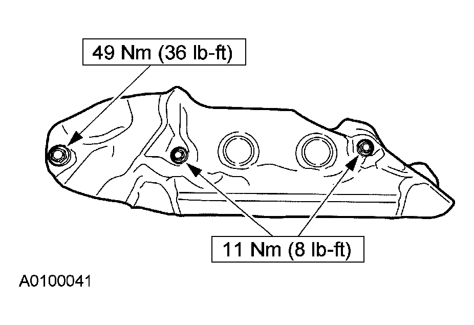 Courtesy of FORD MOTOR CO.
- Release and position the turbocharger outlet pipe.
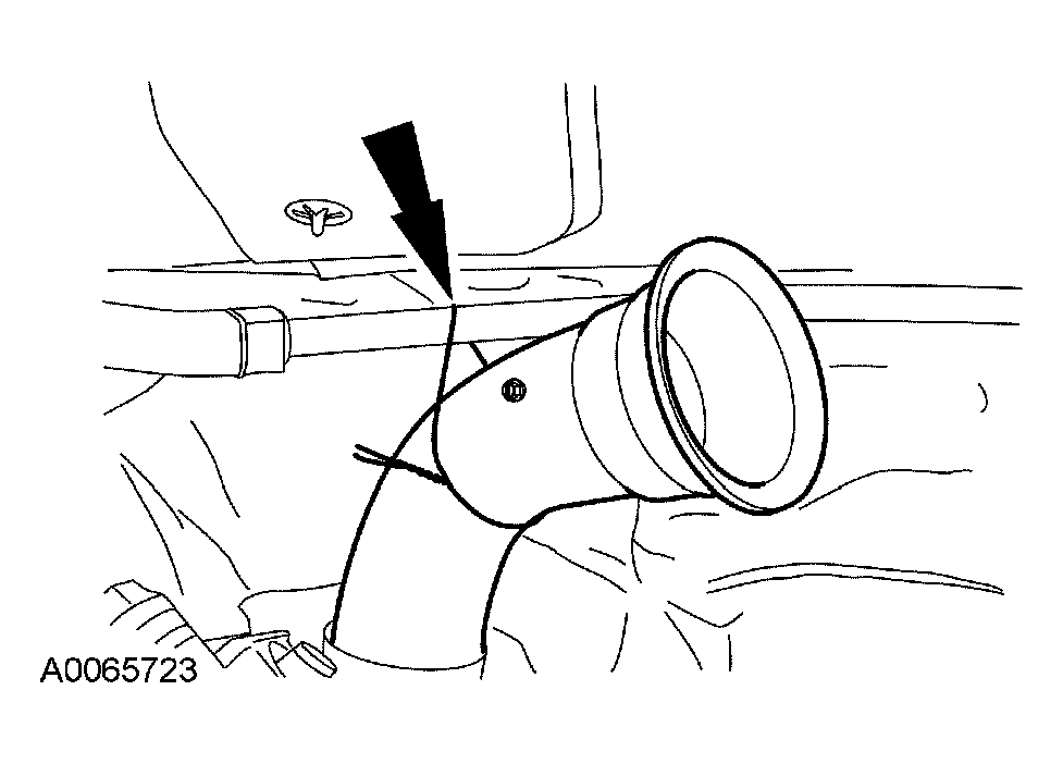 Courtesy of FORD MOTOR CO.
- Install the turbocharger inlet Y-pipe. For additional information, refer to EXHAUST SYSTEM
.
- Install the intake manifold. For additional information, refer to ENGINE - 6.0L DIESEL
.