Pinpoint Test M: The Traction Control Switch Indicator Is Never On
- M1 CHECK THE POWERTRAIN CONTROL MODULE (PCM) OPERATION
- Disconnect: PCM C175b.
- Key in ON position.
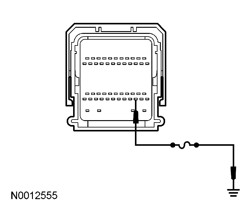
- Connect a fused (10A) jumper wire between the PCM C175b pin 37, circuit 960 (BK/LB), harness side and ground.
 Courtesy of FORD MOTOR CO.
- Does the traction control switch indicator illuminate?
- Yes
: GO to M6.
- No
: GO to M2.
- M2 CHECK CIRCUIT 960 (BK/LB) FOR AN OPEN
- Disconnect: LCM C2145b.
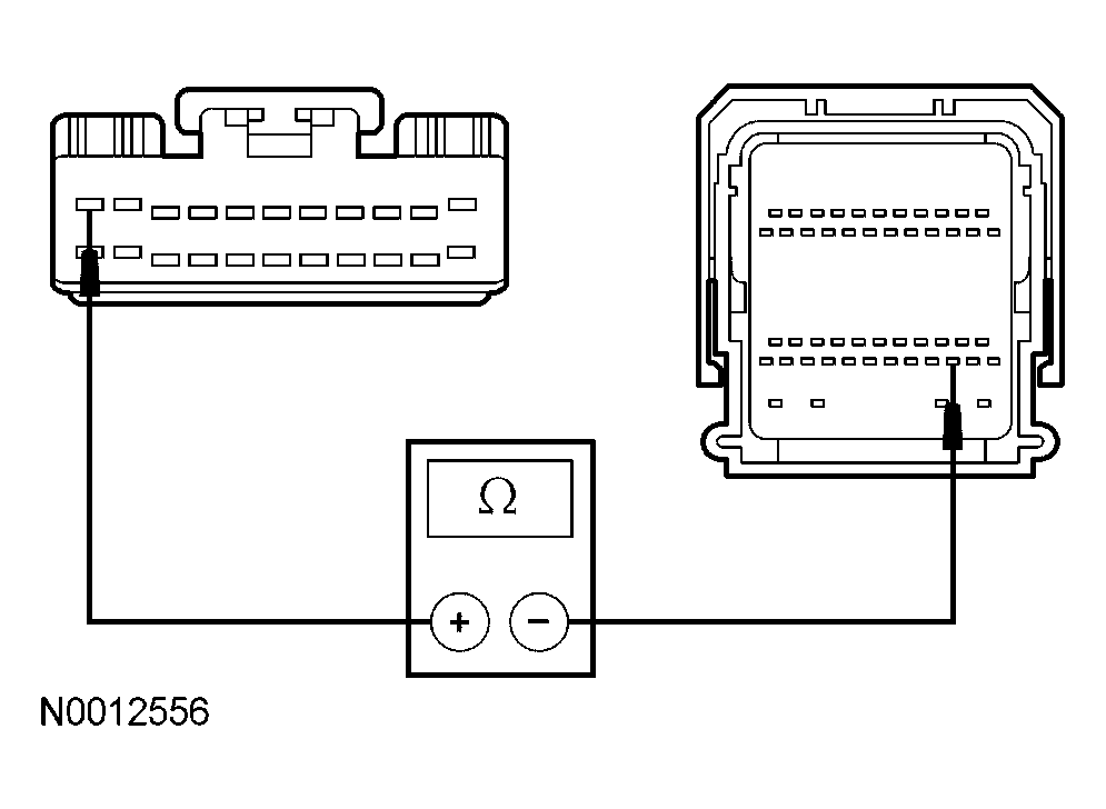
- Measure the resistance between the PCM C175b pin 37, circuit 960 (BK/LB), harness side and the lighting control module (LCM) C2145b pin 1, circuit 960 (BK/LB), harness side.
 Courtesy of FORD MOTOR CO.
- Is the resistance less than 5 ohms?
- Yes
: GO to M3.
- No
: REPAIR the circuit. TEST the system for normal operation.
- M3 CHECK THE LIGHTING CONTROL MODULE (LCM) OPERATION
- Disconnect: LCM C2145b.
- Key in ON position.
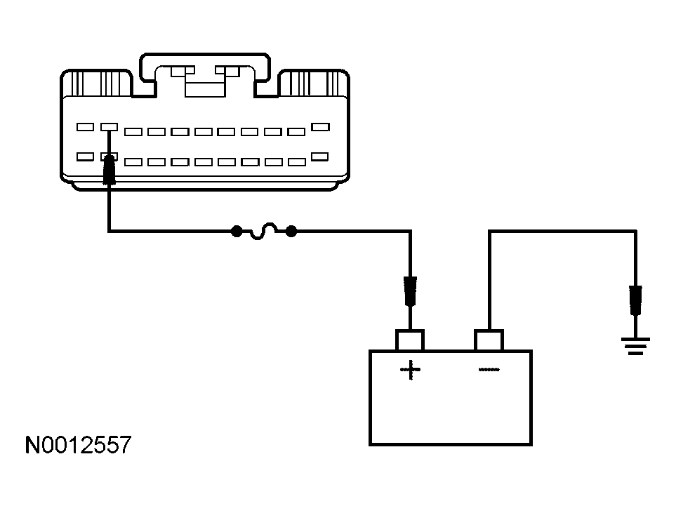
- Connect a fused (10A) jumper wire between the LCM C2145b pin 2, circuit 961 (WH/PK), harness side and battery voltage.
 Courtesy of FORD MOTOR CO.
- Does the traction control switch indicator illuminate?
- Yes
: GO to M9.
- No
: GO to M4.
- M4 CHECK CIRCUIT 57 (BK) FOR AN OPEN
- Key in OFF position.
- Disconnect: Traction Control Switch C280.
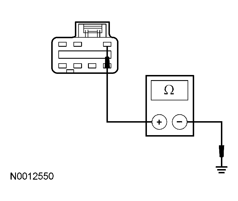
- Measure the resistance between the traction control switch C280 pin 7, circuit 57 (BK), harness side and ground.
 Courtesy of FORD MOTOR CO.
- Is the resistance less than 5 ohms?
- Yes
: GO to M5.
- No
: REPAIR the circuit. TEST the system for normal operation.
- M5 CHECK CIRCUIT 961 (WH/PK) FOR AN OPEN
- Key in OFF position.
- Measure the resistance between the traction control switch C280 pin 4, circuit 961 (WH/PK), harness side and the LCM pin 2, circuit 961 (WH/PK), harness side.
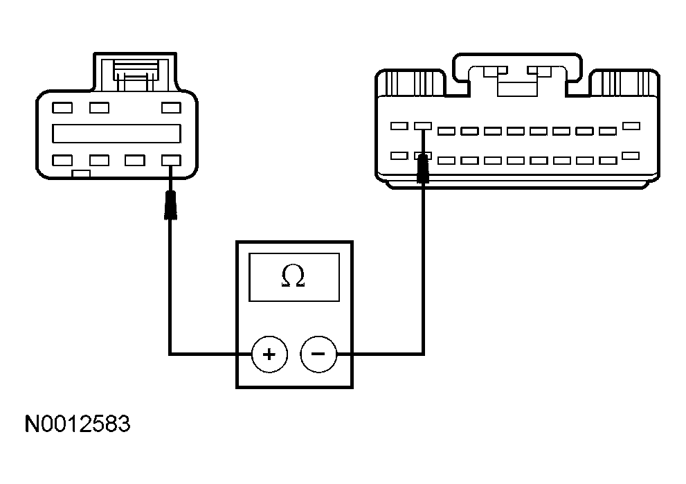 Courtesy of FORD MOTOR CO.
- Is the resistance less than 5 ohms?
- Yes
: INSTALL a new traction control switch. TEST the system for normal operation.
- No
: REPAIR the circuit. TEST the system for normal operation.
- M6 CHECK THE TRACTION CONTROL SWITCH OPERATION
- Key in OFF position.
- Disconnect: Traction Control Switch C280.
- Measure the resistance between the traction control switch pin 1, component side and the traction control switch pin 2, component side while pressing and releasing the traction control switch.
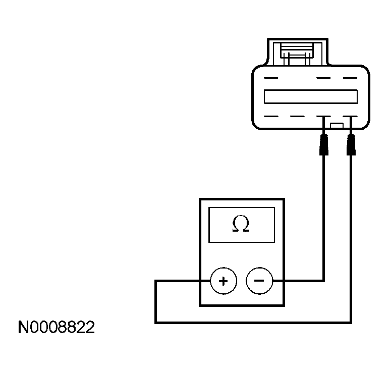 Courtesy of FORD MOTOR CO.
- Is the resistance less than 5 ohms with the traction control switch pressed and greater than 10,000 ohms with the traction control switch released?
- Yes
: GO to M7.
- No
: INSTALL a new traction control switch. TEST the system for normal operation.
- M7 CHECK CIRCUITS 57 (BK) FOR AN OPEN
- Disconnect: Traction Control Switch C280.
- Measure the resistance between the traction control switch C280 pin 2, circuit 57 (BK), harness side and ground.
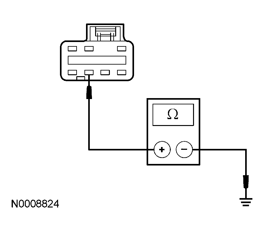 Courtesy of FORD MOTOR CO.
- Is the resistance less than 5 ohms?
- Yes
: GO to M8.
- No
: REPAIR the circuit. TEST the system for normal operation.
- M8 CHECK CIRCUIT 959 (GY) FOR AN OPEN
- Disconnect: ABS Module C135.
- Measure the resistance between the ABS module C135 pin 11, circuit 959 (GY), harness side and the traction control switch C280 pin 1, circuit 959 (GY), harness side.
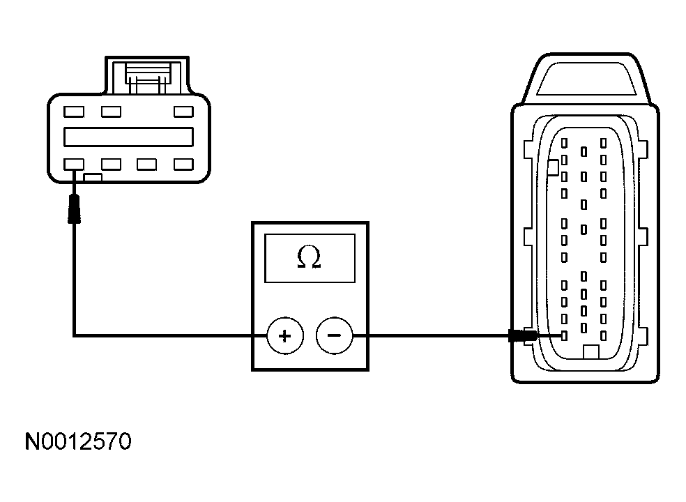 Courtesy of FORD MOTOR CO.
- Is the resistance less than 5 ohms?
- Yes
: INSTALL a known good ABS module. TEST the system for normal operation. If the traction control switch indicator operates correctly GO to M11. If not, GO to M10.
- No
: REPAIR the circuit. TEST the system for normal operation.
- M9 CHECK FOR CORRECT LCM OPERATION
- Disconnect all the LCM connectors.
- Check for:
- corrosion
- pushed-out pins
- Connect all the LCM connectors and make sure they seated correctly.
- Operate the system and verify the concern is still present.
- Is the concern still present?
- Yes
: INSTALL a new LCM module. REFER to MULTIFUNCTION ELECTRONIC MODULES
. CLEAR the DTCs. REPEAT the self-test.
- No
: The system is operating correctly at this time. The concern may have been caused by a loose or corroded connector. CLEAR the DTCs. CARRY OUT the self-test with the brake pedal not applied.
- M10 CHECK FOR CORRECT POWERTRAIN CONTROL MODULE (PCM) OPERATION
- Disconnect all the PCM connectors.
- Check for:
- corrosion
- pushed-out pins
- Connect all the PCM connectors and make sure they seat correctly.
- Operate the system and verify the concern is still present.
- Is the concern still present?
- Yes
: INSTALL a new PCM. REFER to ELECTRONIC ENGINE CONTROLS
. CLEAR the DTCs. REPEAT the self-test.
- No
: The system is operating correctly at this time. The concern may have been caused by a loose or corroded connector. CLEAR the DTCs. REPEAT the self-test.
- M11 CHECK FOR CORRECT ABS MODULE OPERATION
- Disconnect the ABS module connector.
- Check for:
- corrosion
- pushed-out pins
- Connect the ABS module connector and make sure it seats correctly.
- Operate the system and verify the concern is still present.
- Is the concern still present?
- Yes
: INSTALL a new ABS module. REFER to ANTI-LOCK BRAKE SYSTEM (ABS) MODULE . CLEAR the DTCs. REPEAT the self-test.
- No
: The system is operating correctly at this time. The concern may have been caused by a loose or corroded connector. CLEAR the DTCs. REPEAT the self-test.