Disabling System
- Turn all vehicle accessories off. Turn the ignition switch to off. At the Central Junction Box (CJB), located below the left side of the instrument panel, remove the Restraints Control Module (RCM) fuse F2.12 (15A) from the CJB.
- Turn the ignition on and visually monitor the air bag indicator for at least 30 seconds. The air bag indicator will remain lit continuously (no flashing) if the correct RCM fuse has been removed. If the air bag indicator does not remain lit continuously, remove the correct RCM fuse before proceeding. Turn the ignition off.
- Disconnect the battery ground cable and wait for one minute. Remove the driver air bag module. See DRIVER AIR BAG MODULE . Label each driver air bag module electrical connector before disconnecting. Connect 2 Air Bag Simulators (418-F395) to the clockspring side of the driver air bag module electrical connectors. See Fig 1. See AIR BAG SIMULATOR .
- Push in on the glove compartment sides, releasing the stops and lowering it out of the way. Through the glove compartment opening, disconnect the passenger air bag module electrical connector. Connect Air Bag Simulator (418-F403) to the harness side of the passenger air bag module electrical connector. See Fig 2. See AIR BAG SIMULATOR .
- Separate the passenger side "C" pillar trim panel. Disconnect the passenger side safety canopy module electrical connector, located on the "C" pillar behind the second row safety belt shoulder height adjuster. Connect Air Bag Simulator (418-F088/105-R0012) to the vehicle harness side of the passenger side safety canopy module electrical connector. See Fig 3. See AIR BAG SIMULATOR .
- Separate the driver side "C" pillar trim panel. Disconnect the driver side safety canopy module electrical connector, located on the "C" pillar behind the second row safety belt shoulder height adjuster. Connect Air Bag Simulator (418-F088/105-R0012) to the vehicle harness side of the driver side safety canopy module electrical connector.
- Install the RCM fuse F2.12 (15A) to the CJB. Connect the battery ground cable.
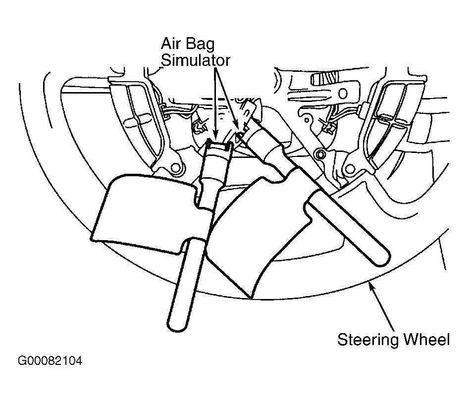 Courtesy of FORD MOTOR CO.
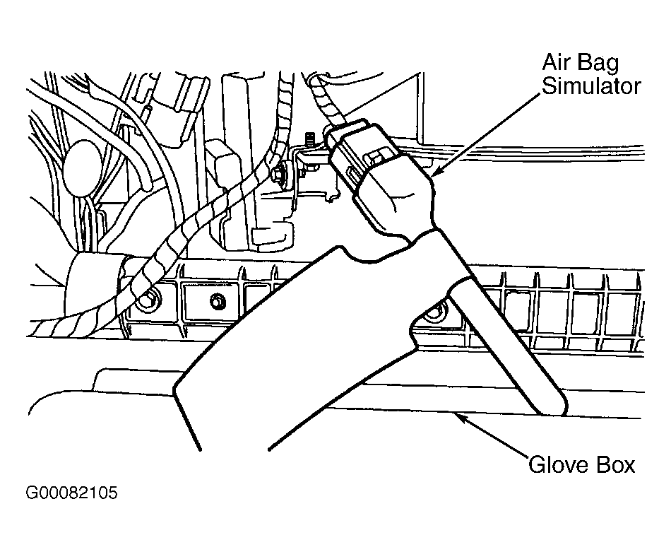 Courtesy of FORD MOTOR CO.
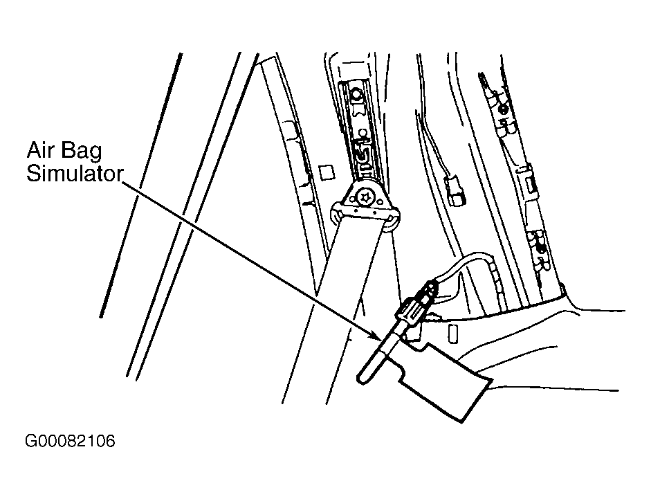 Courtesy of FORD MOTOR CO.